Meet Analysis Situs 2024.1
Intro
On behalf of our small but dedicated crew, I'm pleased to announce that the new version of Analysis Situs has seen the light of day. This software is mainly driven by our belief in open-source Bushido and our will to stay away from walled commercial gardens. Analysis Situs is evolving not only as an end-user application but also as an engineering SDK for CAD developers. It accumulates algorithms for feature recognition, general-purpose solid and surface modeling, data interoperability, and shape interrogation. Read on for a sneak peek at what has been added in the latest release.
- You can download the Windows x64 installer here.
- Visit the official website of Analysis Situs at www.analysissitus.org.
- All changes logged: CHANGELOG.
Kudos to contributors
Let us begin with the most important part. I.e., thanking the community people who volunteered their time and code to the project between ver.1.1 and ver.2024.1:
- JohannesV shared his Dockerfile to build the Analysis Situs UI.
- Steven van der Schoot sanitized our clunky C++ code quite a bit.
- liza-kr (Elizabeth), Julia, Sergey, Natalia and Andrey devoted much of their time to different features of the project, starting with the UI and ending up with complex algorithms.
- gAdlike made a fix for the Quick Hull 2D algorithm.
I must say that contributing to a project like Analysis Situs is not a little thing. A contributor should possess strong skills in both C++ and CAD geometry, not to mention struggling with the intricate architecture of the specific codebase. Personally, I approach each and every contribution with the utmost respect and attention, trying to avoid situations where a merge request is stalled indefinitely. It still happens, but I'm hoping that the long delays from patching to integration have a positive side effect (although it might sound like a terrible excuse). The extensive growth phase of Analysis Situs is about over, and it's probably time to move on to intensive development, which is all about depth and nothing about speed (much like math).
Infrastructure/Configuration
A great deal of time has passed since the previous release. Analysis Situs has been a shaped product for a number of years already, but it's still a little challenging to describe what this software does in a couple of words. A possible analogy might be OpenCascade's DRAW "test harness," which is a prototyping console for geometric modeling. DRAW's design, which is plugin-oriented, is remarkable. A system that is supposed to be extended in a number of unknown ways must support plugins in its DNA. A plugin-oriented architecture also makes it easier to ship commercial add-ons independently of the FOSS base. Analysis Situs is a sort of successor for DRAW, so plugins play a vital role in this project. Therefore, let's begin our review from the engine room and talk about plugins, architecture, and configuration.
Loading custom plugins from `asi-plugins` directory
When Analysis Situs starts, it looks for plugins in a specific directory named asi-plugins located in the working directory. Each dynamic library found there (whether it is dll on Windows or so on Linux) is being searched for a function named PLUGINFACTORY. If such a function is found, the corresponding library is treated as a plugin, and the detected function gets invoked.
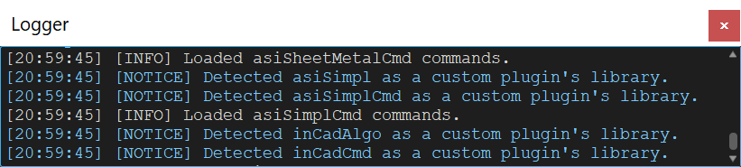 |
It is common practice to use plugins in order to add specialized features to the core functionality (we do it by adding custom Tcl commands). We have a separate repository called "Extensions" where we collect useful plugins. Analysis Situs ver.2024.1 improves the plugin loading mechanism quite a bit. First and foremost, it makes plugins operational on Linux, where historically we did have some troubles. It's worth mentioning that plugins are loaded with the help of OpenCascade's OSD_SharedLibrary class, which gives a cross-platform interface for working with dynamic libraries.
Migration to OpenCascade 7.6.0
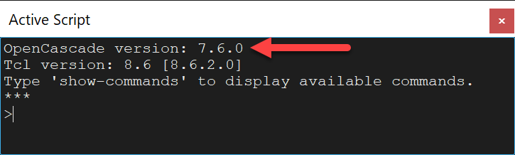
The previous version of Analysis Situs (ver.1.1) was built on OpenCascade 7.4.0, whereas the new version is based on OpenCascade 7.6.0. The used OpenCascade version is now displayed in the console, so you can quickly check what's under the hood. It did not come as a surprise that porting was not particularly smooth. The vendor harmed BREP format compatibility and, even worse, messed up a few things related to color transfer in data exchange. Still, some fixes in STEP import for SolidWorks-originated files were too appealing to not pick them up. Another motivation was to integrate the Analysis Situs SDK into some third-party OpenCascade-based programs where we couldn't choose the core version and had to utilize what was already there. Migration to OpenCascade 7.7 was also partially tested, but we did not proceed with it at this time.
 |
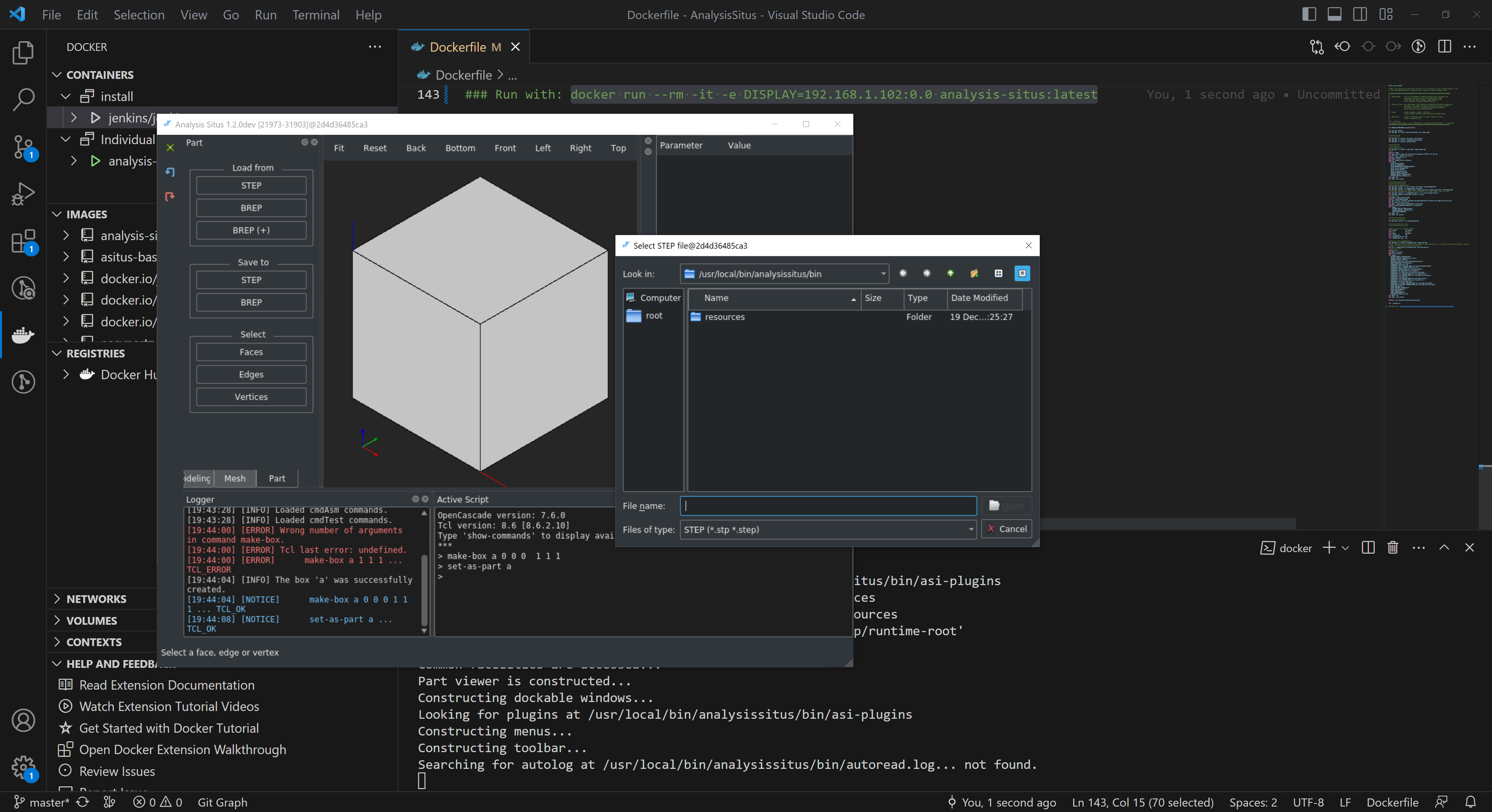
Dockerfile for UI version
Next up, the community member JohannesV contributed a complete Dockerfile for Analysis Situs UI on Linux Ubuntu 20.04. And, guess what, it just worked. After a while, we ported the procedure to OpenCascade 7.6, but the entire thing largely remained as it was. Be aware that this Dockerfile will compile VTK and OpenCascade libraries from scratch, so the whole process takes a lot of time. On Windows with VcXsrv Windows X Server (download here), you can test the Linux build by supplying the DISPLAY option to your Docker container, which is initialized with your local IP address (this topic is covered in our YT lesson 6).
 |
What we are still working on is creating an AppImage to run Analysis Situs as "portable" software. If you rather want to compile Analysis Situs natively, go ahead and read our "Compilation Guides for Linux."
Memory leaks
We took time to carefully hunt down memory leaks in the application. Some of the leaks were induced by OCAF, while others appeared trickier. Read our story on sanitizing memory leaks to learn more.
Algorithms
Evolution of Analysis Situs largely follows the R&D directions outlined in the following posts:
- A proposal for GSoC at OCC (has never been accepted).
- Short list for the FOSS modeling perspectives.
- On geometric modeling perspectives outside commercial software packages (plenary talk at the University of Tomsk).
After years, I can confirm that we were able to stay on track with such a fuzzy "roadmap" despite the fact that it has never been clearly formalized. Depending on the interest exposed by the users, one R&D direction may take precedence over another, and so it goes over time. Here are the main topics on which we worked between ver.1.1 and ver.2024.1:
- Feature recognition.
- Advanced surface modeling.
- Specialized UI.
Construct solid bodies for negative features
This algorithm is based on OpenCascade's generic face removal operator. The goal is to re-trim the "support" faces surrounding a specific feature for constructing a volumetric cell. As a result, we construct a "negative body" that may be utilized to simulate a material removal feature. In addition, the same technique can be used in CFD workflows to obtain a spatial domain for further meshing.
 |
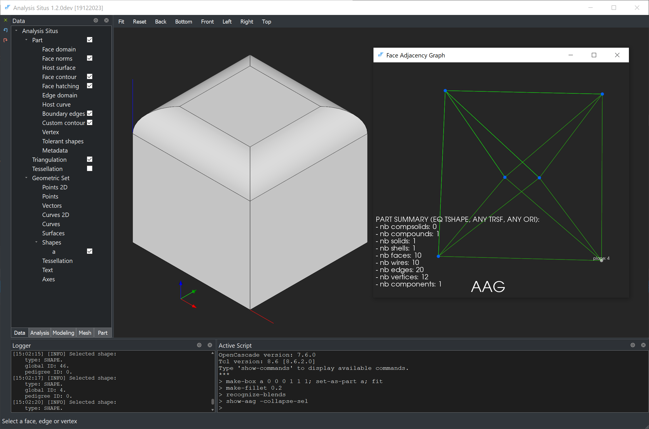
Attributed Adjacency Graph (AAG) improvements
Here is a short list of improvements in the core Attributed Adjacency Graph (AAG) functionality:
- Add Collapse() method in the C++ API for virtual collapsing of graph nodes.
- Add possibility to request optional vertex adjacency relations in AAG.
- Add "face UV bounds" AAG attribute for the sake of caching in performance-sensitive applications.
- Add "non-manifold" dihedral angle type.
AAG is a key ingredient for all feature recognizers incorporated in Analysis Situs. The ability to collapse features while preserving neighborhood relationships between graph nodes is the key conceptual improvement. In the following example, all blends are virtually collapsed, so the model's AAG appears identical to the adjacency graph of a plain box shape. As a result, a CAD model remains untouched while its AAG gets simplified. The collapse procedure opens the door to virtual defeaturing, which kind of resembles the concept of "virtual topology" employed in some commercial meshing software.
 |
Surface fitting to unstructured point cloud
This feature deserves another post or two, but I'm still not satisfied enough with the math behind it. Nonetheless, the technique is quite practical in its current state, and it can be utilized for constructing spline surfaces from scattered point clouds. A few things to draw your attention to are listed below:
- The solved problem is the minimization of a quadratic energy-like functional, with the only unknowns being the control point coordinates. As a result, it is a linear problem, and you, as a user, are responsible for configuring the B-spline basis parameters, such as degrees and number of spans. Therefore, constructing a good surface is a "trial and error" process with no automated magic in the algorithm itself.
- The fairing coefficient is another parameter that can be adjusted. Setting higher values will result in more visible surface smoothing. Just make sure to avoid using too small values, as the linear system may become ill-conditioned, resulting in wild geometry.
- You can use points (provided in the UI table) and the active part's edges as approximation constraints. If edges are used, they are discretized with the specified precision, and this way they are also turned into point constraints.
 |
The new "Fit surface" dialog offers two methods of approximation:
- PLATE (native OpenCascade's surface interpolation method developed by Andre Lieutier).
- APPSURF2 (our in-house approximation algorithm).
Join edges
To concatenate 3D edges in the viewer, there is now a specific algorithm available via the context menu. The algorithm allows for the preparation of a curve network for subsequent Gordon surfacing, although it is not specialized to Gordon and can be used in other situations equally well.
 |
Gordon surface
Martin Siggel deserves credit for including the Gordon surfacing algorithm in the open-source TiGL package. That was a truly scholarly contribution to the field, as, I think, Gordon surfaces had never been publicly exposed in the FOSS world before TiGL. We spoke about Gordon surfaces and their math in the dedicated article. Our intention to include them in Analysis Situs was to apply the "transfinite interpolation" technique to complex geometries, such as turbine blades.
 |
At the same time, as practice proved, Gordon's global approach is not the best for truly curved geometries since it requires the reapproximation of lengthy curves to give them compatible parameterizations. As a result, while "basic" Gordon is now available in Analysis Situs, we will think about it more thoroughly in the future and try to implement a "local" version of the same thing.
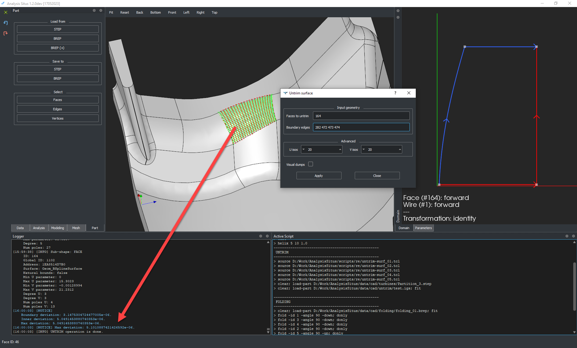
Surface untrimming (UNTRIM)
Trimmed surfaces are supported by the majority of CAD systems. Still, in some cases, having spline surfaces in their "natural bounds," i.e., without trimming contours, could be more preferable. Such simplified topology-free representations could aid in geometry preparation for FEA/CFD as well as in data exchange scenarios, particularly with legacy CAD systems. The UNTRIM operator, which was recently implemented in Analysis Situs, has been inspired by the similar feature in Cimatron-IT, an old-schoolish piece of software (that reminds me of Euclid). In the following picture, we have a trimmed surface selected and untrimmed:
 |
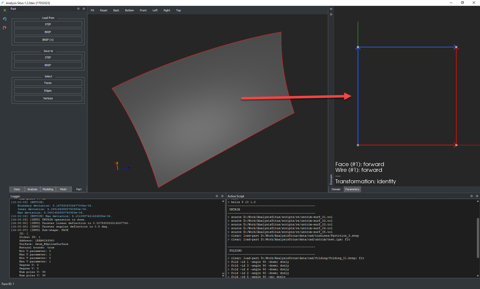
As a result, the untrimmed surface gets defined in a plain rectangular domain, where all pcurves follow along the "natural" isoparametric lines of a surface:
 |
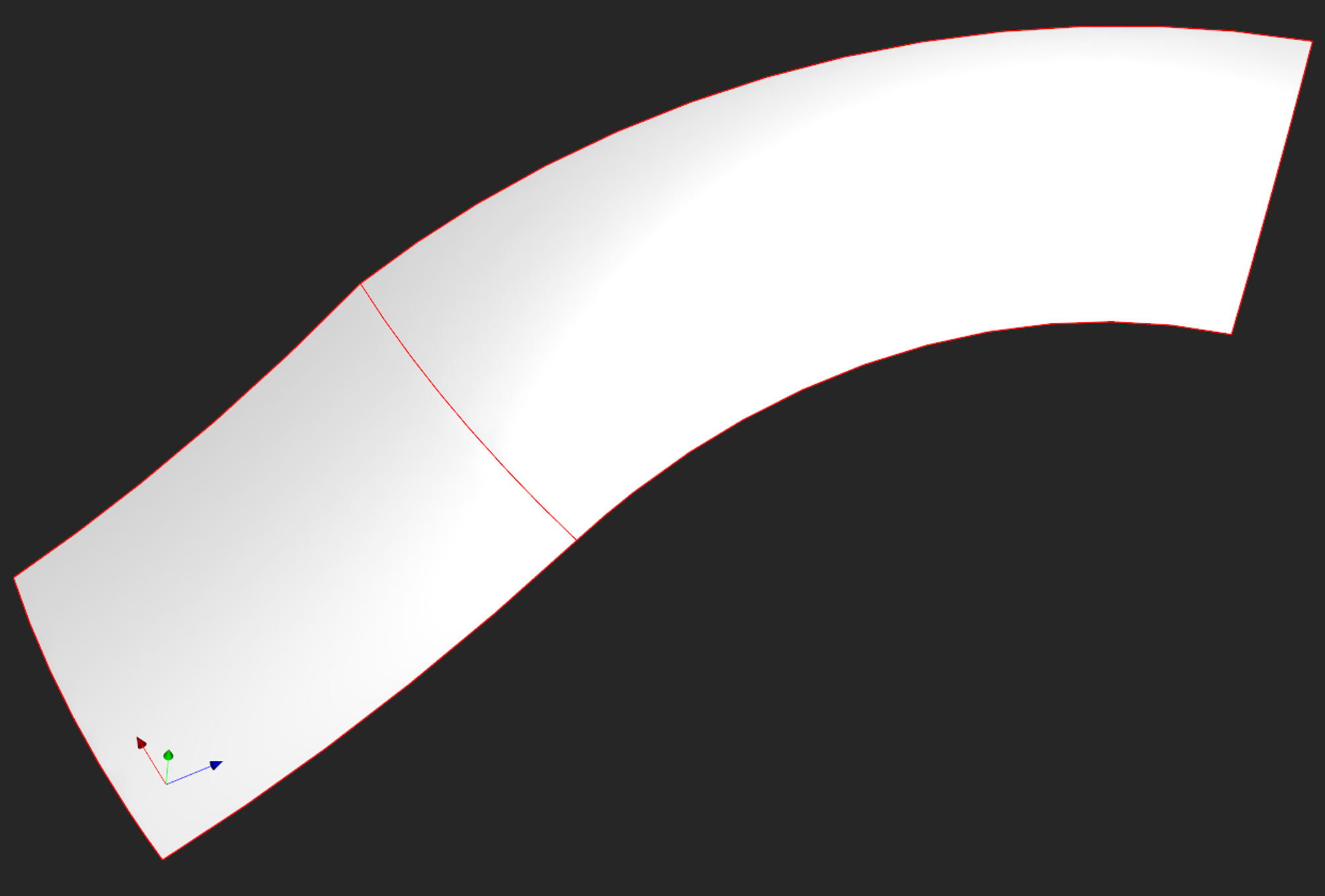
The untrimmed surface is created by interpolating a curve network projected onto the original surface, as shown in the first image. This is where the Gordon apparatus comes in handy for tackling a somewhat unrelated problem.
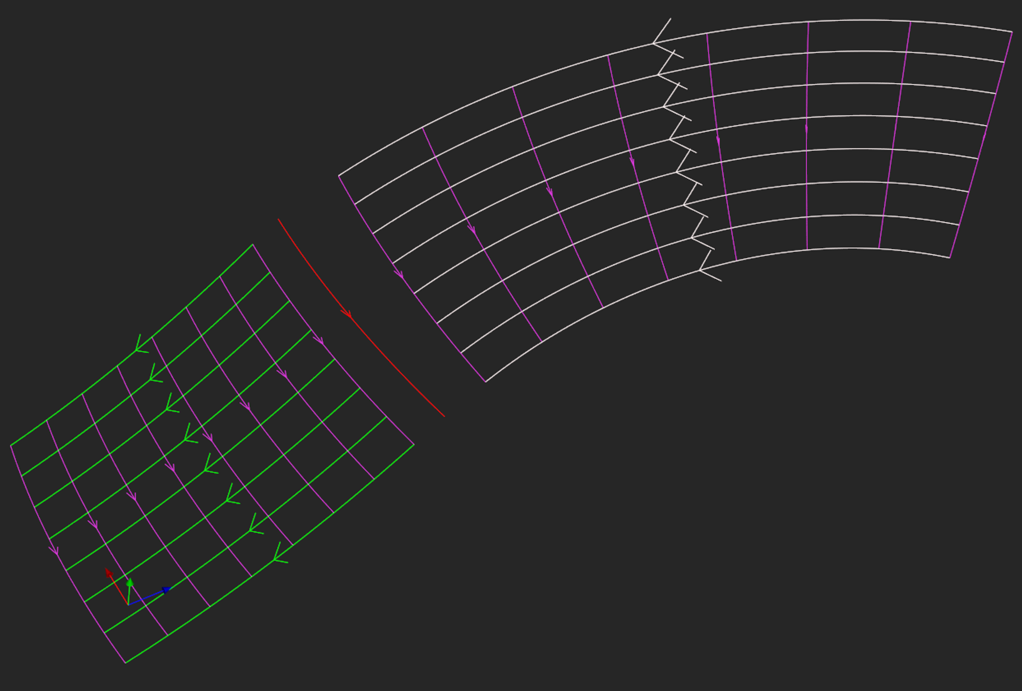
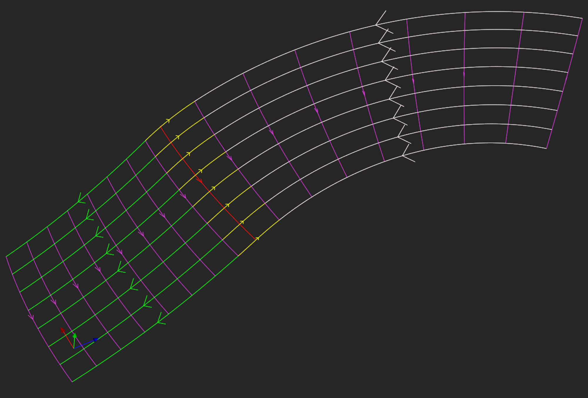
Surface concatenation (JOINSURF)
Given a couple of untrimmed surfaces located next to each other, we can apply the Gordon apparatus to concatenate them into a single surface. This process is quite delicate as it assumes that you understand how your surfaces are parameterized (well, this is where the visualization of Analysis Situs should actually help).
 |
The first step of the JOINSURF algorithm is to shrink the operand surfaces near their common curve. Such shrinking is actually nothing to do because our surfaces are already defined in their natural bounds (if not, then the UNTRIM operator should be applied beforehand). This trick allows you to "cut off" possible anomalies, which can often be found near the CAD model's edges.
 |
The second step of the JOINSURF algorithm is to prepare the curve network based on the isoparametric curves of the operand surfaces and construct a Gordon surface.
 |
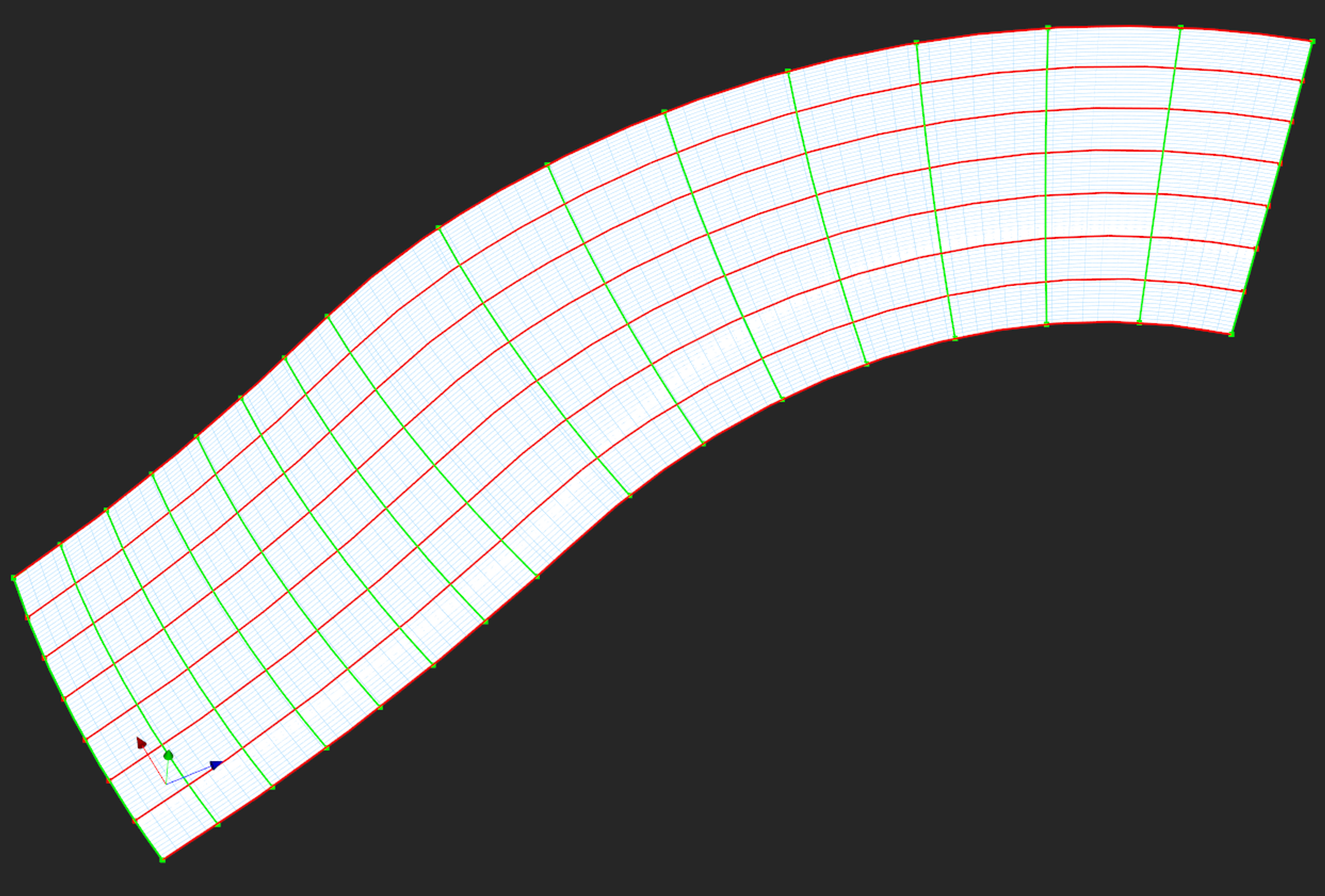 |
Using a combination of UNTRIM and JOINSURF, we can concatenate spline surfaces with reasonable accuracy and better control than in the REPATCH operator (that performs surface fitting).
 |
Concatenate pcurves
This functionality was covered in a separate article, where we also discussed the necessity of sewing and UV scaling. The following animation is an example of a somewhat extreme case for concatenation. The single-curve contour obtained in this example is not quite suitable for subsequent modeling due to its continuity defects, but it demonstrates the principle of concatenation.
 |
Smart reorientation
Coming back to feature recognition scenarios, let's look into the newly introduced orient-part command and its underlying algorithm. The objective behind this feature is to find a better placement for the active part while taking its inherent symmetries into account. The technique is not based on inertia axes, as one might expect, but rather on "light" feature detection, such as checking cylinder axes, plane normals, and so on. This algorithm outputs a local axis frame that is "baked into" the part. Once this local reference is identified, the part can be moved into a better position by aligning its local frame with the global axes. This type of relocation is equivalent to a rigid body transformation.
 |
Such a reorientation algorithm is especially useful in CAM, where we often wish to evaluate the dimensions of a stock shape. If the position of the part is not optimized, the corresponding bounding box (or bounding bar) will almost certainly overestimate the real physical size of a stock.
Recognize linear extrusions
The convert-to-canonical function of Analysis Situs attempts to turn freeform curves and surfaces into canonical representations. That's a pretty important function that is strictly required for reliable feature recognition, but not only there. Another application for canonical conversion is direct editing (including defeaturing), as it is far easier to modify a canonical part than a part full of splines. This algorithm has long been accessible in Analysis Situs, and with the latest release, it now recognizes and converts the surfaces of linear extrusions. We dedicated an entire post to this development because it appears to be highly essential, particularly for CAM feature recognition.
 |
Healing for planar contours
There is a new tool implemented in asiAlgo_ConvertCurve namespace aimed at improving the quality of 2D contours. This feature is indirectly related to our sheet metal series, where we often wish to generate flat patterns of unfoldable parts. The new tool provides an API for the following operations:
- Convert a contour to a polygonal representation.
- Convert a contour to a series of lines and arcs: misc-convert-curves.
- Check for gaps in a contour: misc-check-gaps.
- Fix gaps: misc-repair-gaps.
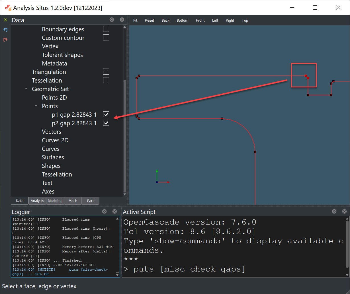 |
These features are designed to be used programmatically, although we added the corresponding Tcl commands for testing purposes. The ultimate idea behind these algorithms was to prepare a 2D drawing for such procedures as nesting or simply make the cutting paths machining-ready. In specialized CAM software, all contours must be coded as lines and arcs with no substantial gaps between consecutive segments. If gaps exist, there are two ways to get rid of them:
- Apply ShapeFix_Wire shape healing tool of OpenCascade and let it do what it does. This is the purpose of misc-repair-gaps command. Be aware that this tool will turn the dangling edges into splines to give them more flexibility and then move the extremity control points to close a gap.
- Convert a contour with our in-house misc-convert-curves algorithm. This tool will not only turn all splines into arcs and lines, but it will also make sure to stitch the converted segments to each other. As a result, all potentially existing gaps between splines would naturally disappear. Be aware that gap filling would not apply to canonical curves in that case.
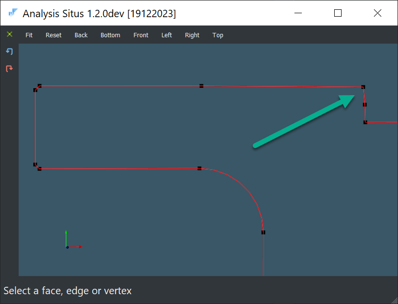 |
Mesh slicer
A slicer is an essential part of any 3D printing toolkit. Consider Slic3r as an example of a community project focused on providing open access to the geometric API required to print a model. Although 3D printing has never been a top concern for Analysis Situs, we realized that it's valuable to have a slicer algorithm for a variety of use cases. After all, a mesh-based slicer is a fast technique to generate two-dimensional sections of a model. It is similar to executing OpenCascade's BRepAlgoAPI_Section algorithm but orders of magnitude faster. For example, a slicer algorithm might help in detecting whether a loaded CAD part is of prismatic shape or not (we use such logic in recognizing metal profiles).
 |
The algorithm is implemented in asiAlgo_MeshSlice utility class.
Miscellaneous
We introduced a number of other improvements and bugfixes that would take too much space to describe in detail, while their "global" contribution is not that visible. You may want to head over to the textual CHANGELOG to see the complete list. A few other things to draw your attention to are given below:
- Blend face vexity is now reported in the fillet recognizer. We can now tell if a blend face is concave, convex, or has mixed (saddle-like) vexity.
- Conical edge-blend-faces can now be optionally recognized as fillets.
- Drilled hole recognizer has been improved quite a bit to allow for toroidal subfeatures.
- We introduced an algorithm to convert spline curves and surfaces to 3-degree Bezier segments.
- More handy functions have been added to the asiAlgo_Utils namespace, including IsConical(), IsStraight(), IsCircular(), GeneratePixmap(), CacheFaceUVBounds(), IsTypeOf(), ConnectEdgesToWires(), ComputeFaceLength(), CacheFaceRange(), Str::AmendedFilename().
- The RTCD package has been extended with IntersectRayAABB() and IntersectRayPolyhedron for point-to-bbox and point-to-hull distance checking.
- The RTCD's AABB can now be initialized from a two-dimensional OpenCascade's bbox.
UI
As mentioned above, the UI of Analysis Situs has been modified to provide greater flexibility in typical usage scenarios. This does not necessarily mean that the user interface has become more ergonomic, clean, or "MS Office"-like. Absolutely not. The user interface is still clunky, but if you have ever used Cimatron or Salome, you shouldn't be scared. The trouble is, Analysis Situs is more of a developer's tool than an end-user software (much like OpenCascade's DRAW). Having said that, I'm still sure that we can improve it and (at least) sanitize some unnecessary UI controls in future releases.
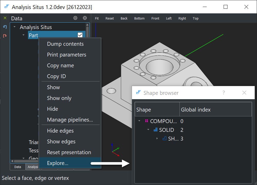
Shape exploration
To quickly check the contents of an active part or a shape from the "Geometric Set" (renamed "Imperative Viewer" section), you can use the "Explore..." context-menu action. This action opens a tree view populated with all subshapes of the selected shape. Each item can be displayed alone and turned into the active part for subsequent inspection.
 |
Project clean-up
To erase everything from the active project, use clear command or a little icon in the top-left corner.
Fast defeaturing
To quickly defeature the selected group of faces (which may have been returned by one of the automatic feature recognizers), use the "Del" key. Pretty much like in Fusion360.
 |
JSON editor
Many algorithms in Analysis Situs are intended to export their results in JSON format (though this does not necessarily happen in the UI). To serve this purpose, we have created a specialized JSON editor dialog that incorporates the following features:
- Syntax highlights and collapsible sections.
- Inline search.
- Automatic JSON validity checker.
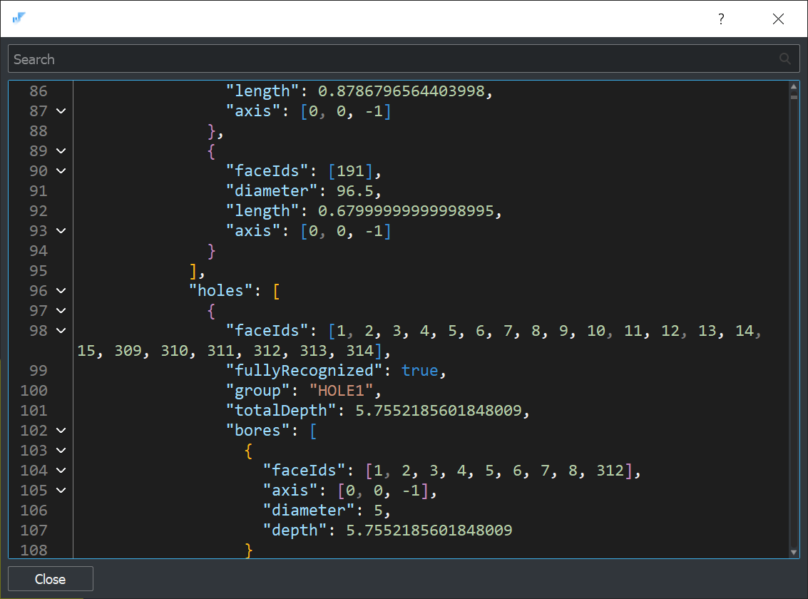 |
A specialized viewer with JSON format validation, syntax highlighting, and collapsible sections, similar to those found in VS Code, has been proven handy. The font size of the JSON viewer can be changed by using the mouse wheel with the "Ctrl" key pressed or the "Ctrl" and ↑ or ↓ keys simultaneously.
Face/Edge/Vertex finders
Normally, you would copy the face IDs reported as features and use them to locate the corresponding groups of faces in the 3D viewer. The search dialog invoked by the "Ctrl + F" combination is normally utilized to find faces by indices. To make things easier, you can drop numerical IDs with random separators and sloppy characters. The indices will be extracted from your input with an embedded regexp.
 |
Context-menu actions
- We added the possibility of checking precise thickness by clicking on a face.
 |
- A couple of specific context-menu actions are now available for checking duplicated face IDs in features ("Check for common faces" and "Check for repeated faces"). While "Check for repeated faces" determines whether each pair of features has a common face, "Check for common faces" can be used to determine whether all of the selected features have a common face and, if so, what those faces are. The results of these checks can be seen in the log window.
- "Fit all" context menu action is now available in all 3D/2D viewers.
Miscellaneous
Again, CHANGELOG has far more information than we can post here. It's weird, but our WordPress-like engine begins to lag as I write this, which has never happened before (that's because of the size of this post). Should we release more frequently to avoid this?
- Edges can now be selected in the wireframe visualization mode. In addition to that, all faces can be selected with the "Ctrl + A" key combination.
- We introduced help command to print a command usage hint.
- Face/edge IDs are now shown on mouse hover in the status bar.
- Multiple selected Nodes can be deleted from the "Data" browser.
- More parameters are now exposed in the Parameter Editor for the available Nodes. E.g., it is now possible to configure the number of UV isolines in the Hatching Node, better control curvature combs for edges, rescale vector fields, and much more.
- We fixed the plot 2D dialog that was incorrectly rendered on Linux.
- We massively redesigned the command list dialog to make it more user-friendly. As more and more commands have been added to the command list, there has been a significant side effect of scrolling until you reach the desired item. This prompts us to consider a search option that would enable instantaneous access to a requested command. Moreover, hovering the mouse over the command name displays a tooltip with an explanation of the command. Type show-commands in the Active Script panel to check out the refined dialog.
More console commands
Almost every new feature of Analysis Situs starts its lifecycle in the incubator of a Tcl command. Some features keep belonging to the Tcl terminal and never make it to the GUI, which, I guess, is fine because otherwise our UI would quickly become horizonless. Here's a brief digest of especially useful commands:
- The dfbrowse would let you see the low-level OCAF contents of the current project.
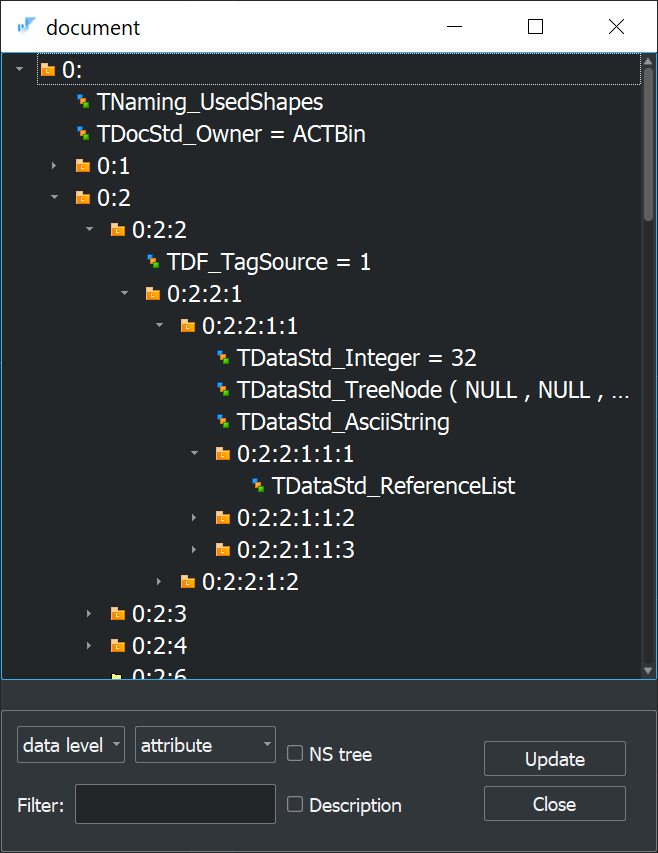 |
 |
- My favorite Tcl command is the newly introduced dump-autoread that hibernates the contents of the scripting panel, so that the next time you run Analysis Situs, it gives you the same script as you had in the previous session (#123).
- check-facets Tcl command has been added for checking the validity of facets within a part (#127).
- The newly introduced asm-xde-unload command allows to break down assemblies into individual part files.
Interoperability
- IGES import for XDE documents.
- Fixed subshape names coming from STEP files (#258).
- New "Scene Tree" data structure for assemblies together with serialization/deserialization logic.
The XDE interface has seen three essential upgrades: one allows reading STEP files with subshape names; another allows loading IGES files into internal XDE documents; and the third allows dumping assembly hierarchy to JSON format along with serialization/deserialization of B-rep geometry. See the corresponding help page for further information on saving assembly structures in JSON format.
P.S.
Before posting these massive release notes, we made a "last-minute" decision to reconsider version tagging. Rather than issuing another ver.1.x, we decided to make things a little cleaner and favored the YYYY.N format, where YYYY is the year and N is just the serial number of a release inside that year. As a result, the next version will be 2024.2, or just 24.2 for brevity. The same versioning approach is employed in Datakit products (for CAD interoperability), and it looks quite smart.
It remains to wish our readers a happy New Year 2024. "Stay vertical" no matter what. Take care.
Want to discuss this? Jump in to our forum.