How to assess the complexity of DXF drawings
Automatic feature recognition on drawings
Previously, we discussed some technical aspects of DXF drawing generation utilizing the XDE data framework included with OpenCascade. We created drawings using the sheet metal unfolding algorithm and ensured that they included information about bending in a commonly accepted format (a distinct layer with dashed lines at folds). Today, let's look at technical drawings from a new angle.
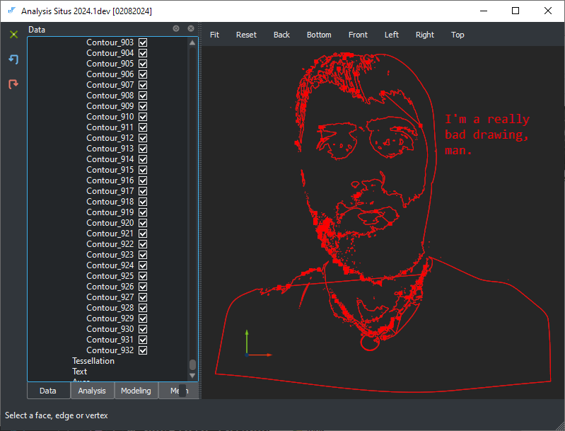 |
DXF drawing may contain all sorts of garbage. According to the method presented below, the complexity of this drawing is 6.644 (with a certain set of predefined weights), which means that this drawing is probably too complex to pass it through an automatic recognition workflow. |
Let's put drawings in the context of automatic feature recognition. Unlike STEP files, the geometries communicated via DXF format are way less restricted as long as this format does not require the represented shapes to be consistent in whatever sense. You can literally drop any sort of garbage inside the file and your DXF viewer will happily open it up. The problems will show up later:
- CAM software will not process invalid or "dirty" contours coming with the drawing file.
- Your automatic quotation tool will fail to recognize any features in the drawing.
- Loading and processing of huge DXF files will take forever.
- Whatever else "garbage in / garbage out" story you can think of will happen.
As we agreed to talk about drawings in the context of feature recognition, let's postulate the need of design rules for any incoming drawing file.
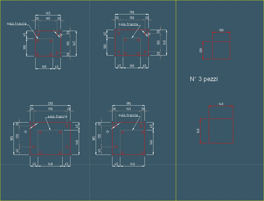 |
DXF drawing that does not follow hypothetical design rules for automatic feature recognition. |
The drawings like the one above would challenge any feature recognition algorithm because:
- There are several layers, and it is unclear which ones correspond to the parts and which are supplementary (markings, engravings, bend lines, annotations, dimension lines, etc.).
- There may be a frame (with or without a table) surrounding the part(s).
- A single drawing could contain many parts.
- The geometries of "useful" contours can have gaps, dirty overlaps, ambiguities, and so on.
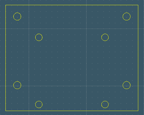 |
DXF drawing well prepared to feature recognition. |
Checking if a drawing is "concise enough" for automatic processing is fairly difficult. Just looking at the file size tells you nothing about its contents, and running feature recognition without a timeout (which is another problem) can result in unexpected timing. Therefore, the question is if we can estimate the complexity of a drawing before submitting it to automated processing pipelines.
Basic complexity metrics do not work
So, how can we assess the complexity of a drawing file without performing a visual inspection and geometric translation of the contents? The following metrics can easily be extracted for any DXF file:
- File size.
- CPU/wall time for file import.
- Number of elements in the imported model (before geometric conversion).
The graph below depicts the wall time spent checking these metrics across about 1000 cases. Although the check duration is clearly dependent on the drawing complexity, it never surpasses a fraction of a second (see the values over the vertical axis), allowing it to be safely called even for large drawings without the risk of the app stalling.
 |
DXF complexity evaluation for ~1k different test drawings. |
Alright, this measurement is fast, but is it useful? How well do these metrics reflect a drawing's actual complexity? Is there a true correlation between the number of entities in a DXF file and its processing time on feature recognition? To answer this question, let's have a look at two graphs simultaneously: one is the wall time spent on feature recognition for a DXF drawing (red plot); another is the number of entities in the DXF file (green plot, scaled to thousands for clarity):
 |
DXF feature recognition for ~1k different test drawings. |
The number of entities can be computed in different ways. In the above plot, we just count all distinct elements of a drawing file which got their corresponding C++ data structure as a result of file import. We could also exclude non-geometric entities from consideration assuming that their influence on the processing time is less significant (which is not that obvious). We can see that correlation between timing and the number of entities is clearly absent. The timing for a relatively small drawing can be around 20 seconds (if not worse), while the number of entities is around nothing. If we had correlation, then the green spikes on the graph above would have followed the red spikes (with different amplitude).
Aggregated complexity score
The aggregated complexity metric $M$ for a DXF file might be expressed as a weighted combination of basic metrics:
$M = s ( w_1 M_s + w_2 M_t + w_3 M_e + ...$ )
Here $w_i$ are the calibrated weights, $M_s$ is the file size, $M_t$ is the processing time, $M_e$ is the number of entities. The final metric is scaled by the factor of $s$ for convenience. The weight coefficients $w_i$ should be calibrated w.r.t. a specific version of feature recognition algorithm. They express "sensitiveness" of the algorithm's performance to different factors, such as the presence of text entities in the DXF file or whichever else basic metric $M_x$ you would want to add to the estimation procedure.
 |
Some better correlation thanks to aggregated complexity metric. The alignment of peaks is still not perfect, but the computed metric can already be used to predict drawing complexity. |
What correlation actually means is that we can now judge the complex problem by solving a simple one: instead of running heavy feature recognition, let's first check the correlated complexity to see if we need to use more computation power, warn the user about a long-running process, run the job in the background, or even reject the job.
One major takeaway from this exercise is that the complexity score is more tied to the processing algorithm than to the drawing itself. This metric aims to capture the correlation between data complexity and algorithm performance, which is, of course, dependent on how well the algorithm is optimized with respect to various data characteristics, such as the presence of texts, layers, splines, etc.
A similar kind of a "score" can also be derived for solid geometries, and it is intuitively clear that such a metric should be bound to the production method. I.e., a part having many faces is not necessarily hard to fabricate, e.g., if a part can be done on a lathe machine. Vice versa, a part having a small number of faces might be very tricky to make if it does not follow some basic technological rules, e.g., it has angled pockets instead of prismatic ones. So, deriving a complexity score for CAD geometry (whether it is a planar drawing or a 3D file) requires the availability of a feature recognition algorithm, which should be used to calibrate numbers.
Want to discuss this? Jump in to our forum.