On sheet metal unfolding. Part 11: bend grouping
- Part 1 gives an introduction to unfolding and reviews the software packages for solving similar tasks.
- Part 2 explains how bends can be unrolled precisely.
- Part 3 instructs how to survive the K-factor.
- Part 4 outlines the structure of the unfolding algorithm. It also introduces the notions of the "unfolding tree" and the "border trihedron" which are essential ingredients of the solution.
- Part 5 introduces a generalized unfolding algorithm that can handle rolled parts and parts with specific design issues, such as terminating or consecutive bends.
- Part 6 is the introduction to another challenging problem of sheet metal processing, which is bend sequence simulation.
- Part 7 discusses how to treat machined holes in a way to generate accurate flat pattern contours.
- Part 8 gives some topological heuristics to distinguish round tubes from rolled pieces.
- Part 9 introduces the concept of "dynamic unfolding" for bending simulation.
- Part 10 highlights the importance of recognizing non-isolated cutouts in folded sheet metals.
How to group bends?
An intelligent CAM for sheet metal bending goes beyond recognizing individual bends and predicts folding operations in the same way that a human operator would conduct them. Normally, when checking several bend features to be done in one folding operation, we verify the equivalence of the following properties:
- Angle,
- Axis,
- Inner radius,
- Direction (UP or DOWN).
If these properties are identical, then the corresponding bend features can potentially be combined into a single bend line, and this way we can reduce the manufacturing effort. It is, of course, decided in the shop floor whether to group bend features together or not, but the software can predict how many folding operations are required in the [close to] optimal case. The same principle can be used to make production drawings a bit more concise as we do not have to generate specifications for every identical bend in a raw.
 |
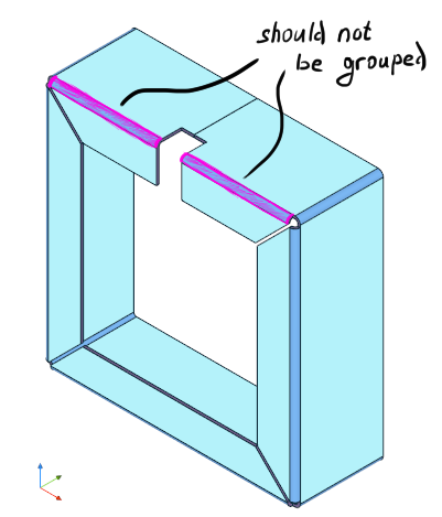
However, such property-based grouping does not capture the situation when bends are hosted by completely separate flanges. Look at the following image, where grouping by geometric props is clearly a bad idea:
 |
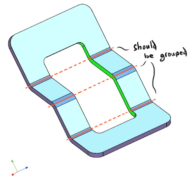
It becomes clear that bend grouping should take into account not only the geometric props, but also the topology of a part. But how do we capture this? The bends to be grouped do not necessarily share any flanges, which can be seen from the following picture:
 |
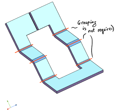
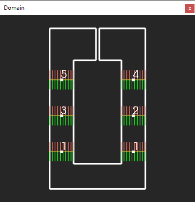
Also, it is enough to add a single cut to the part illustrated above to make this grouping requirement entirely optional (to group or not is to be decided by a human operator):
 |
In the first case (where grouping is required), our bend lines belong to a loop of flanges, so that each next flange depends on the previous one, and there is a topological circuit between the dependent flanges. The difficulty of detecting such situations is the difficulty of searching for circuits in graphs, which is a well-understood problem in the graph theory. Unfortunately, direct search methods are computationally prohibitive, which was proved by our experience in finding circuits in the so-called FTG graphs.
Folded cutouts as topological hints
We found it fairly interesting to make use of the topology of folded cutouts to constrain bend groups. In Part 10 of our "unfolding" series, we looked at how to identify non-isolated cutouts in folded sheet metal parts. We may now use this apparatus for bend grouping, which may sound unusual (after all, how are folding operations dependent on cutouts?).
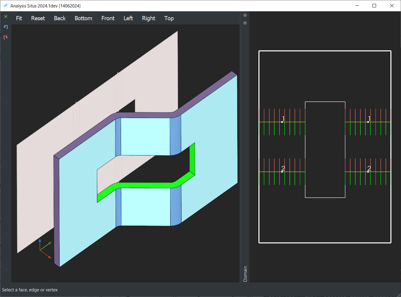 |
The thing is that, topologically speaking, a closed contour of cutting faces (a cutout) is already a loop which corresponds to a circuit of the neighboring sheet faces. Therefore, cutouts are not just geometric features: they locally arrange the topology of a part, and we can build our bend grouping logic on that fact. Look at the following illustration:
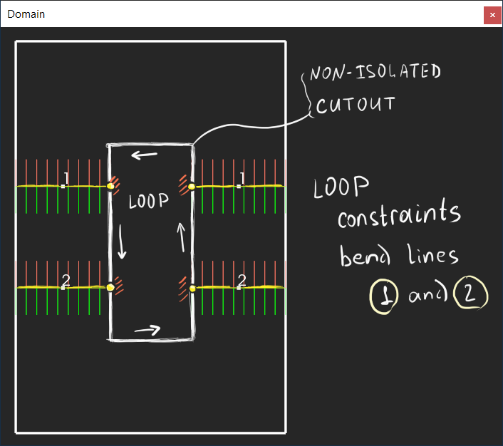 |
There is no way for the bends 1 and 2 to move freely as long as they are constrained with the corresponding cutout ("LOOP" in the image). But if we cut the loop, the constraint wipes away:
 |
Proper bend grouping opens the door to accurate bend sequence simulation, which is the topic we will discuss in our future series.
Want to discuss this? Jump in to our forum.