On sheet metal unfolding. Part 9: dynamic unfolding
- Part 1 gives an introduction to unfolding and reviews the software packages for solving similar tasks.
- Part 2 explains how bends can be unrolled precisely.
- Part 3 instructs how to survive the K-factor.
- Part 4 outlines the structure of the unfolding algorithm. It also introduces the notions of the "unfolding tree" and the "border trihedron" which are essential ingredients of the solution.
- Part 5 introduces a generalized unfolding algorithm that can handle rolled parts and parts with specific design issues, such as terminating or consecutive bends.
- Part 6 is the introduction to another challenging problem of sheet metal processing, which is bend sequence simulation.
- Part 7 discusses how to treat machined holes in a way to generate accurate flat pattern contours.
- Part 8 gives some topological heuristics to distinguish round tubes from rolled pieces.
What is dynamic unfolding?
When we discussed bend sequence simulation, it became clear that to decide on a folding sequence, we should take into account possible tool-part collisions. But that's not enough. In the following illustration, the elevation of the flange f1 on bending would lead to a collision with the already folded flange f2, although the final state of the part is just Okay.
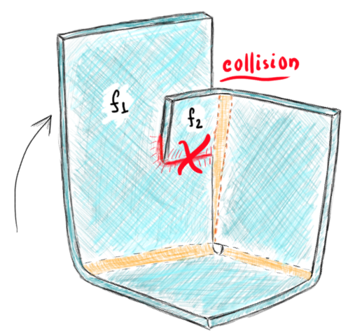 |
Therefore, there are collisions of two types:
- Self-collisions of a part on folding.
- Part-tool collisions.
This observation makes it clear that collisions have to be checked during bending, or we should rather use the swept volumes of the rotating flanges. We need to watch the folding process in dynamics to have an accurate simulation. Up until now, that has never been the case. In both rotation-based and paving-based unfolders, the flanges were dropped to the stationary plane in one shot, i.e., without any time frames involved.
The dynamic unfolding technique allows you to unroll bends frame by frame. Each frame represents an intermediate folded state of geometry that can be used in the collision test. We don't use swept volumes here because they appear less intuitive, whereas frames can be arranged into an easy-to-understand animation.
Data structure
It should be stressed that neither the original B-rep model of the CAD part nor a mesh-based representation allow for simple deformation. To enable dynamic unfolding, we provide an ad hoc representation of a folded state of geometry. In its simplest form, it can be a "hinge" model of the pairs of sheet faces, with bend faces simply left out. In what follows, we call such a flexible model the "Folded State."
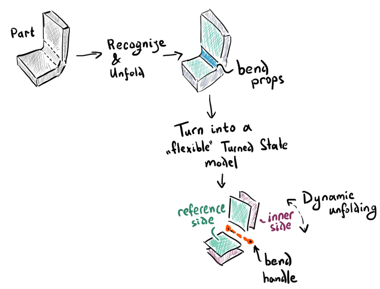 |
We assume that the recognized B-rep model contains everything we need to unfold the geometry flange by flange. Indeed, as a result of recognition, we know all the bend features, their angles, directions and groups. We now need a data structure simply more flexible and convenient in computations than the cumbersome B-rep.
Each bend in the Folded State can serve as an interactive kind of handle. The user may freely select a bend line and apply the folding angle of interest.
 |
The folding angle conventions we use here are the same as those presented in Part 6 for bend sequences: depending on the bend direction ("UP" or "DOWN"), the corresponding flanges around the "hinge" joint elevate or lower with respect to the reference side of the sheet (colored in blue).
 |
From a data structure standpoint, it is critical to reuse all topological relationships between flanges and bends as they appear in the unfolding tree. To enable rapid frame-by-frame simulation, we should avoid any geometric computations, which is undoubtedly possible because a part's topology remains unchanged when folded and unfolded.
On bend grouping
To reduce simulation complexity (but not only for that), similar bend features are often grouped. At the same time, having bends ungrouped leaves more degrees of freedom to the simulator, however increases the computation time, thus we have to group bends carefully.
Folding simulation is used for design validation, which is to assess if a product can be manufactured without collisions. We were surprised to discover certain flaws in the recognition logic when the bend simulator was added to the workflow. We discovered how badly flanges are sometimes grouped in specific cases after allowing them to fold and unfold around. For example, look here:
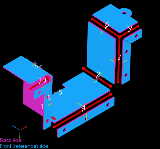 |
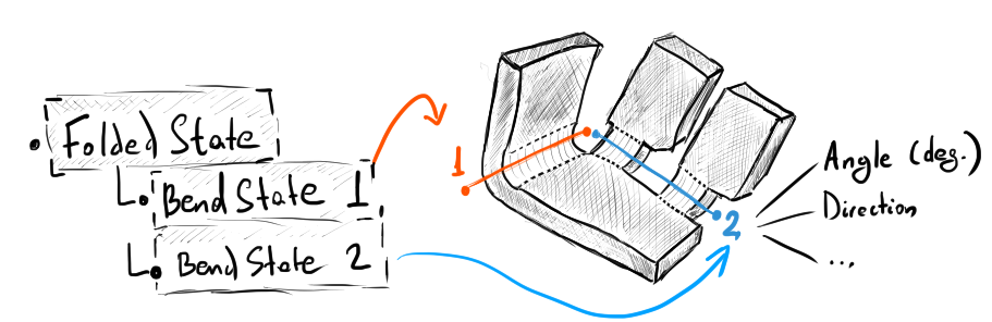
Despite the fact that the bends with IDs 9 and 10 have identical attributes (angle, inner radius, direction, and axis), they should not be grouped together. The issue is that, while these bends appear aligned in the final (folded) geometry, they do not remain aligned during the folding process. This means that the recognizer should not draw conclusions about bend alignment based just on the final state of geometry.
 |
If bend features are grouped properly, dynamic unfolding may easily separate the "left" and "right" sides of a sheet metal part and move them around as rigid bodies. As a result, just inverting the folding angles for each bend feature will bring the simulation model to its flat state. The image below shows a folded sheet metal part loaded from a STEP file and the related simulation model in the flattened state:
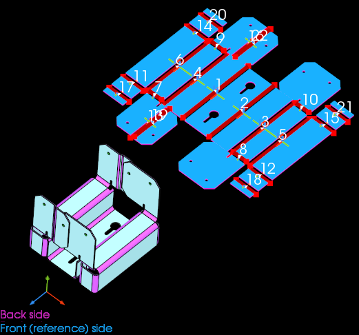 |
And here's how we can progressively unfold a boxy shape, which is, by the way, not quite manufacturable (because of inevitable punch-part collisions):
 |
Notice that the bend features with IDs 8 and 9 could have been incorrectly grouped because they are aligned in the folded state. This way, bending simulator allows us to verify the recognition results.
We will keep talking about bend simulation and what it takes to make a sensible simulation code from an algorithmic point of view in a later series.
Want to discuss this? Jump in to our forum.