Another case with a broken sheet metal part
In this article, I'd like to give a couple of tips for fixing yet another "dirty design" problem. Look at the sheet metal part here:
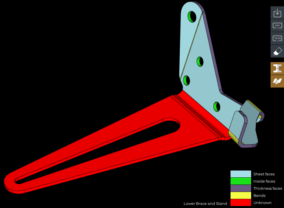 |
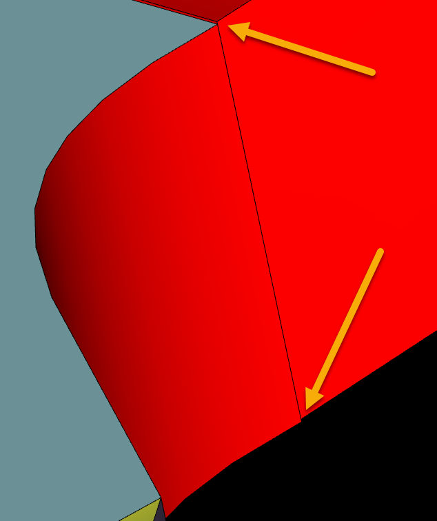
This solid cannot be recognized (as a sheet metal) and unfolded because of a little flaw near one of the bend features. It feels like the two halves were modeled separately and then joined using a solid Boolean operation. Here is this slight (~0.24 mm) shift of one half with respect to another:
 |
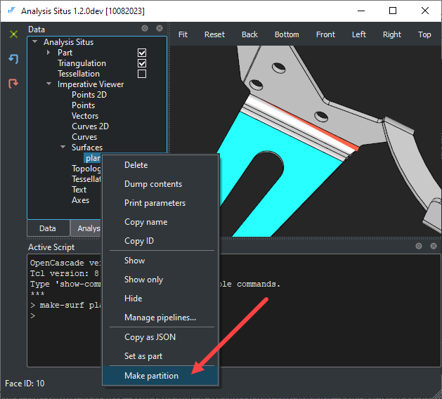
Surprisingly, such defects are quite tricky to fix, maybe because they are not always curable with fancy "push and pull" modeling operators, if you know what I mean. There is a little more to do with a part's geometry to make it clean and practical. We start with partitioning the part, i.e., separating its two halves onto individual solids. To do that, we first have to build a separation plane. In Analysis Situs, you can select a tiny "elevation" face and make a plane out of it using the following command:
> make-surf plane
This command extracts the host surface from the selected face and makes it an explicit variable in the project tree.
|
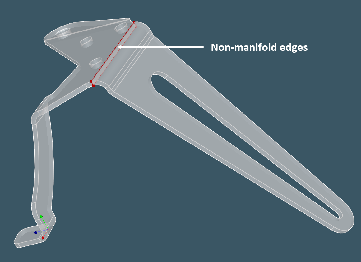
Once the plane is ready, you can use it to partition the model. The idea behind it is similar to that of a standard CAE-ish partitioning, where the goal is to generate non-manifold cells for subsequent FEA. Let's utilize the same apparatus to simply break down one solid into two pieces.
 |
Partitioning turns the initial solid geometry into a couple of non-manifold cells as it can be seen from the following image:
 |
To extract the solid bodies from the partition result, we go like this:
> explode -solid
What I did next is exported both solids to STEP files and opened them in Fusion360 where employed "Assemble / Joint" command to match the opposing faces. It remains then to fuse the parts back, e.g., like this (in Analysis Situs):
> bop-fuse res "SOLID 1" "SOLID 2"
And there we go. The part can now be recognized and unfolded:
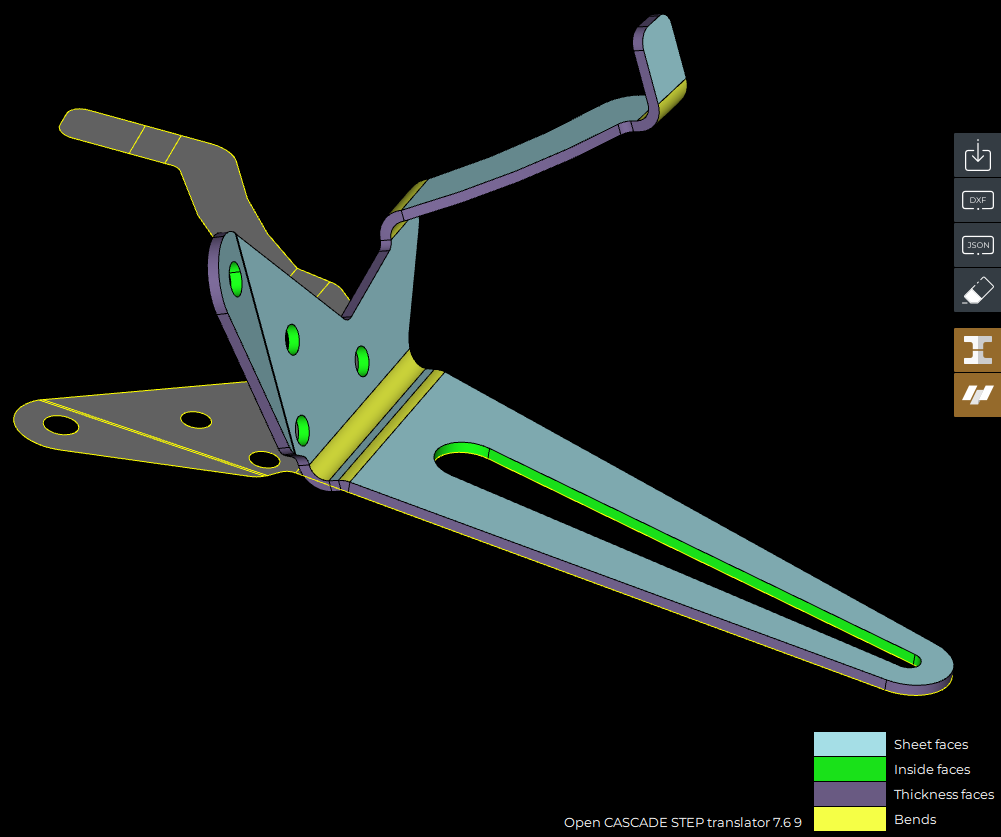 |
Want to discuss this? Jump in to our forum.