- Part 1 gives an introduction to unfolding and reviews the software packages for solving similar tasks.
- Part 2 explains how bends can be unrolled precisely.
- Part 3 instructs how to survive the K-factor.
- Part 4 outlines the structure of the unfolding algorithm. It also introduces the notions of the "unfolding tree" and the "border trihedron" which are essential ingredients of the solution.
- Part 5 introduces a generalized unfolding algorithm that can handle rolled parts and parts with specific design issues, such as terminating or consecutive bends.
- Part 6 is the introduction to another challenging problem of sheet metal processing, which is bend sequence simulation.
- Part 7 discusses how to treat machined holes in a way to generate accurate flat pattern contours.
- Part 8 gives some topological heuristics to distinguish round tubes from rolled pieces.
- Part 9 introduces the concept of "dynamic unfolding" for bending simulation.
Problem
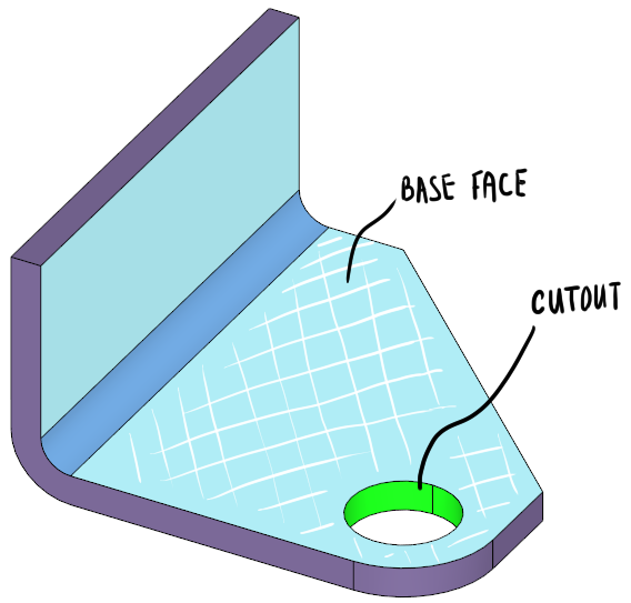
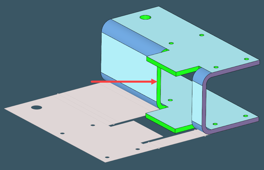
Isolated features are fairly easy to recognize because they leave inner "insertion" contours on the corresponding base faces. Previously, we published a brief study [1], in which every defined feature was assumed to be isolated. This restriction then naturally propagated to our other feature recognition tools, such as sheet metal recognition and unfolding (SMRU). Indeed, conventional cutouts are most typically found in the interior of a base face, like it's shown in the image below:
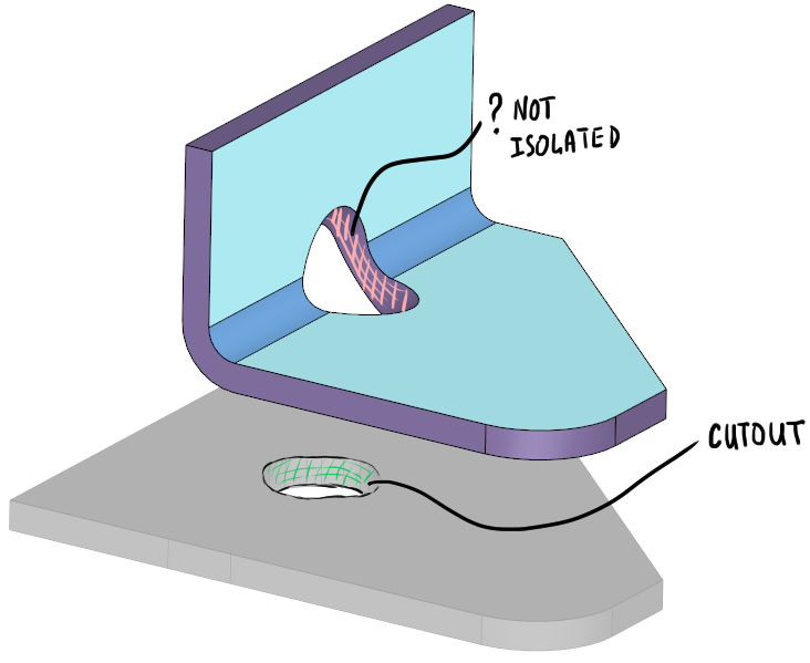
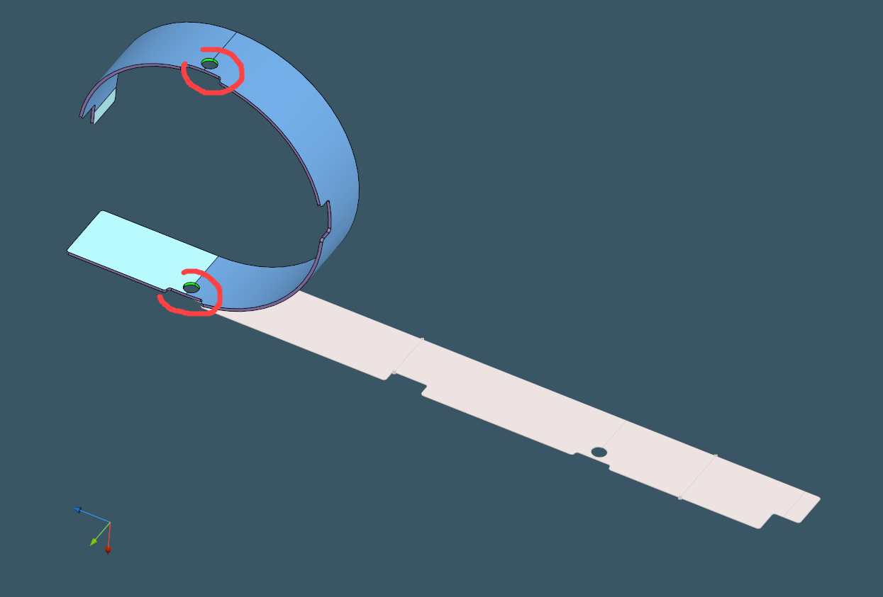
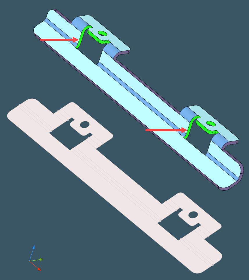
Cutouts are usually made in a flat shape before bending, therefore it does not matter technologically whether a cutout is isolated or not. In the image below, we get a cutout without a specific "base face" around its insertion contour. This base face disappeared once we folded the blank sheet.
This issue is nothing new in CAD, of course. For example, the meshing community is well aware of cross-patch grid generation, which is desired when a mesher should disrespect specific feature edges. So here we have the same issue: who cares whether a cutout is isolated or not? However, when it comes to programming, the "non-isolated" situation is a way more hard to handle.
Solution
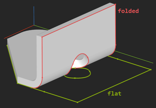
The approach to proper cutout recognition is based on the discovery that non-isolated features are easier to find on the dual flat pattern shape than in the folded 3D geometry. So, if we wish to test a feature insertion contour for being nested inside an outer perimeter contour, we'd better do so in 2D. The key component of the unfolder here is its history of modification. We should be able to extract the flat image of each folded edge to get into the modeling space of reduced dimensionality.
Once we are in 2D, we can set the following heuristics for the folded cutouts:
- Assuming there is always one group of outer perimeter faces, all cutouts contribute smaller bounding box diagonals than the outer perimeter in 2D.
- Cutout contours are always closed.
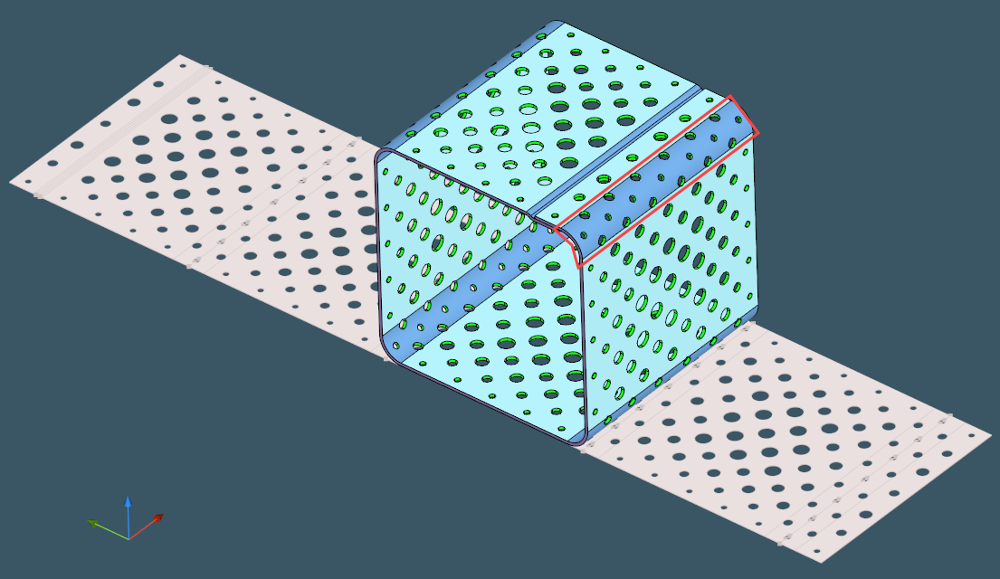
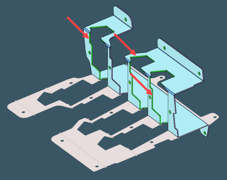
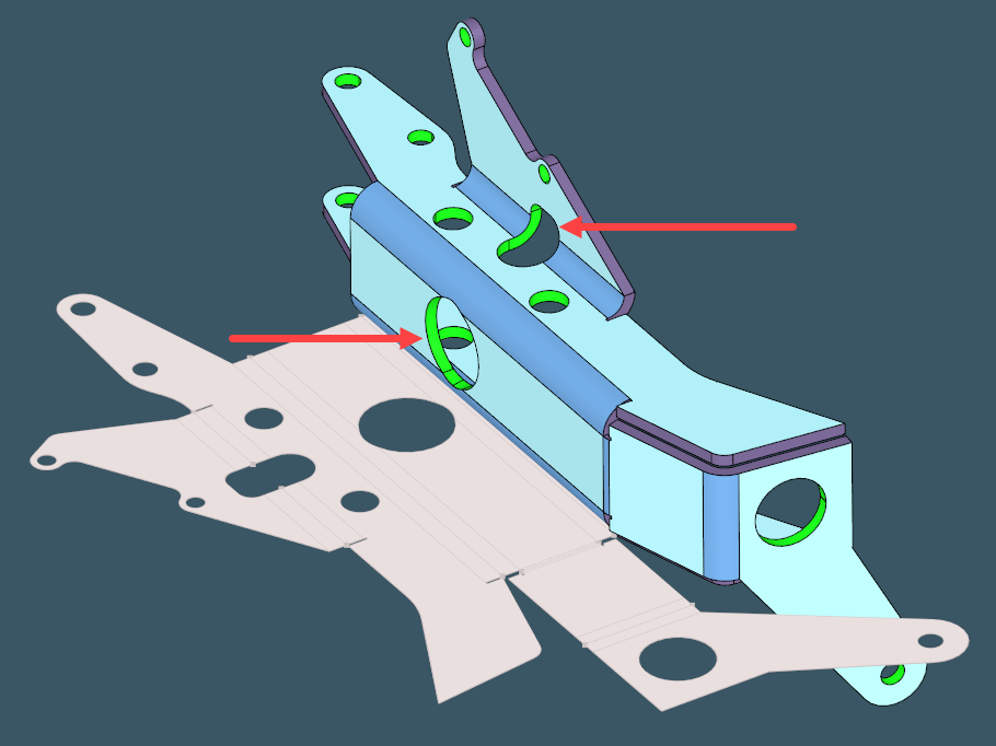
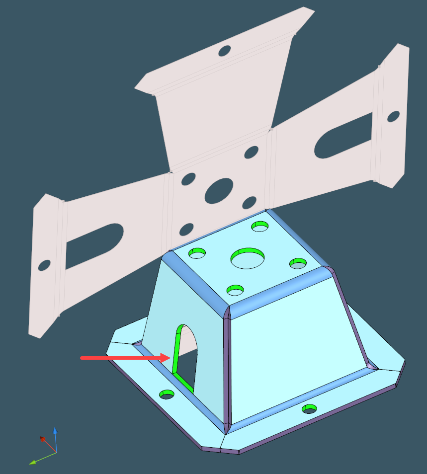
Some examples of folded sheet metal parts with non-isolated cutouts follow:
It appears that the detection of non-isolated cutouts is a "must have" feature of a sheet metal recognition algorithm. The amount of test cases that contain such features is quite extensive: around 160 models out of 2300 files tested in our environment. I.e, almost 7% of all cases do contain such features, while almost none of the cases we have are synthetic, so the database is representative enough to render conclusions over it.
References
- Malyshev, A., Slyadnev, S., and Turlapov, V. 2017. Graph-based feature recognition and suppression on the solid models. GraphiCon 2017, 319-322. (full text).
Want to discuss this? Jump in to our forum.