OpenCascade's XDE for DXF drawing generator
Preface
Let's talk about the XDE framework that we touched on in the previous article. XDE stands for the eXtended Data Exchange module provided by the open-source OpenCascade kernel for representing CAD assemblies and engineering metadata. Other names that are sometimes used for the same thing are XCAF, and even DECAF (Data Exchange CAF).
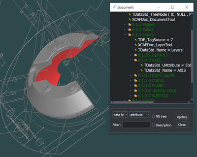 |
Data loaded into an XDE document. |
What XDE brings to the table is a communication medium between different data formats and the OpenCascade kernel. Here's the thing. Regardless of the input format, you can always deal with the same data structure once everything is loaded into an XDE document. This approach is quite standard and is actually implemented in the majority of decent data translation libraries. For example, in the C3D kernel a similar thing would be C3dModelDocument.
As you might probably know, OCC (as a company) provides a range of niche data translators for Parasolid, ACIS, and DXF. All these formats are also loaded into the same format-agnostic XDE data structure, so this framework is also dealt with by paying customers of OCC.
In Analysis Situs, we utilize XDE to enable working with CAD assemblies. The same XDE module is capable of representing metadata, such as colors, names, layers, and even PMI, so it's not necessarily related to assemblies and you can benefit from it in a single-part context. Comprehensive reference documentation on our API is available here: Assembly XDE document.
Continue reading if you want to learn more about XDE from a low-level programmatic perspective.
Fundamentals
These days I've been working with DXF drawings using the commercial DXF translator by OCC, and that implied some XDE-related programming. Practicing XDE felt like a good opportunity to publish some hints for whoever working on the same or similar tasks. In what follows, I'll sometimes switch from the "vanilla" XDE interfaces to the indirection layer provided by Analysis Situs. That's simply because our team has accumulated quite some best practices in working with XDE. Using the native interfaces provided in the original XDE would have stepped us back in the usability of this whole business.
Setting up an XDE document
All XDE-related functionality of Analysis Situs is located in the asiAsm::xde namespace. To create a new document, you go like this:
Handle(Doc) doc = new Doc;
This oneliner allocates the corresponding OCAF document in the heap memory and sets its internal format to "BinXCAF" (the native format of XDE documents in OpenCascade).
Personally, I prefer prototyping new algorithms and procedures in the Tcl language because it allows for visual inspection of geometries and OCAF structures. There's a way to wrap an XDE document with a named Tcl variable that can be addressed later on for inspection. In the C++ function corresponding to a Tcl command, setting up a Tcl variable goes like this (see SetVar() function call):
int NewDoc(const Handle(asiTcl_Interp)& interp,
           int                          argc,
           const char**                 argv)
{
  Handle(Doc) doc = new Doc;
  interp->SetVar( "M", new cmdAsm_XdeModel(doc) );
}
This cmdAsm_XdeModel class is supposed to represent our document in the Tcl session. You might have come across a similar concept in OpenCascade's Draw with its Draw_Drawable3D and Draw_Drawable2D classes. As a result, a new variable named "M" is exposed to the Tcl session, so the user can work with this variable and pass it through different functions. That is what I really like about the Tcl language: you can easily plug it in the C++ code using the provided C API. But I digress. Once the variable is set, we can use its name to address the document, e.g. here:
1> whatis -model M
2> asm-xde-dfbrowse -model M
The second line makes our embedded OCAF browser pull up with the whole bunch of labels and attributes of the XDE document named "M". It's basically nothing but a diagnostic tool you might wanna use to check the internals of your document.
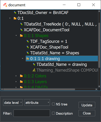 |
OCAF browser. |
To compose a more user-friendly view of the same document you can go like this:
> asm-xde-browse -model M
This command shows the hierarchical contents of an XDE document together with the OCAF IDs of the corresponding parts and components.
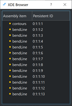 |
User-friendly contents view of an XDE document. |
XDE sections
In a typical XDE document, as provided by OpenCascade, we have the following sections capturing the most common data types (the contents may change depending on the OpenCascade version):
| Commonly used | Label ID / name | Purpose |
| + | 0:1:1 / Shapes | Assembly hierarchy, including individual parts, components and also subshapes for metadata assignment. |
| + | 0:1:2 / Colors | Colors of three types: generic, surface, curve. These colors can be associated with any items from the previous section (0:1:1), although their interpretation is left to the application. |
| + | 0:1:3 / Layers | Layers are mostly useful for composing 2D drawings, although it's possible to have them in 3D scenes as well. |
| - | 0:1:4 / D>s | Dimensions and geometric tolerances for STEP AP242 support. |
| - | 0:1:5 / Materials | Materials, e.g. those coming from a STEP file. |
| - | 0:1:7 / Views | Views for the persistent states of the visual scenes. |
| - | 0:1:8 / Clipping Planes | Clipping planes. |
| - | 0:1:9 / Notes | Notes for design review. |
While the first three sections (Shapes, Colors, Layers) are quite generic, every other group leaves a flavor of being an ad-hoc addendum. If you try to match them up with ISO10303 (STEP), you'll shortly see that the expression power of XDE is definitely less than what you might wanna have in your specific application. For example, how about different geometric representations of the same part? Or alternative assembly graphs? Or what if I wanna have some simulation data, such as boundary conditions associated with subshapes of my parts? Or add some fancy visual attributes, e.g. textures?
Extension points
Fortunately, XDE does not restrict you from adding your own sections right after the predefined ones. Furthermore, it is even possible to customize the contents of existing sections by adding new attributes right near the existing ones. Here XDE benefits from the underlying framework, which is the OpenCascade Application Framework (OCAF). The key to understanding OCAF is taking this framework as a sort of database. It's quite limited because it fully resides in your dynamic memory and does not provide any sort of query language. Still, just like in a database, you are free to add new labels (tables) and alter the existing storage scheme by adding new attributes (columns).
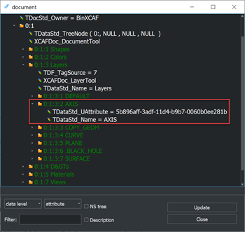 |
Contents of a "Layer" in an XDE document. |
If you come across a limitation in the existing XDE scheme, the first thing to consider is extending it to accommodate your missing data types. Such an approach is likely way easier and faster than rearchitecting the existing XDE-aware software for using a brand new alternative data structure.
Case study: XDE for drawings
But let's come back to a real example that would make this whole story easier to comprehend. I used XDE to represent 2D drawing information so that it can be passed later on to the DXF translator. The questions I've got to answer are basically these two:
- How can we add specific linetypes to layers?
- How can we colorize layers?
The idea behind a layer is to group some meaningful portions of the model geometry so that all the corresponding entities can be edited altogether. If you look at the first screenshot of this article, you'll see tons of construction lines that do not contribute anything to the final solid geometry and are likely supposed for filtering them out. Another example of a layer, which is more traditional, is a layer in a 2D drawing. For example, it is usual to put cutting contours for a sheet metal part in one layer while keeping all bending lines as a separate layer with a different linestyle. The problem I came across is that the OCC DXF writer does not handle linetypes as this data simply does not exist in the XDE predefined storage schema. Let's look at what it takes to bring up a linetype to a DXF-oriented XDE document.
Adding an attribute
So, we agreed that we need to add a linetype property to a specific DXF layer. Technically, according to the DXF format reference, a layer can be associated with a linetype and color. Mapped to the XDE, we express it via custom OCAF attributes associated with the layer's label. A linetype itself is somewhat like the following in the DXF file (for the dashed type):
DASHED
 70
     0
  3
Dashed __ __ __ __ __ __ __ __ __ __ __ __ __ _
 72
    65
 73
     2
 40
19.05
 49
12.7
 74
     0
 49
-6.35
 74
     0
Therefore, to have this information in an XDE document, you would need to create a custom attribute capable of storing all these data. Actually, linetypes are so different that it's wiser to unify their definition in a separate domain object and let the corresponding OCAF attribute just store a handle to this object.
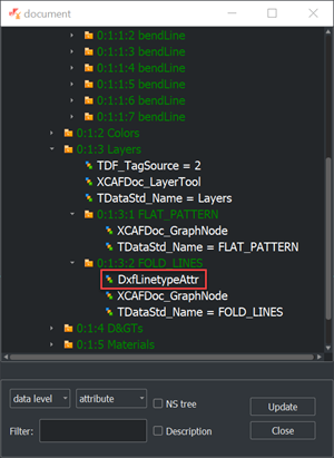 |
Custom linetype attribute in a layer. |
Adding an attribute to a layer is done with generic XDE/OCAF API (here "doc" is our XDE document):
Handle(XCAFDoc_LayerTool)
  layerTool = XCAFDoc_DocumentTool::LayerTool( doc->Main() );

TDF_Label               bendsLayerLab = layerTool->FindLayer("FOLD_LINES");
Handle(DxfLinetypeAttr) linetypeAttr;

// Set linetype attribute to the corresponding layer.
if ( !bendsLayerLab.IsNull() )
{
  linetypeAttr = DxfLinetypeAttr::Set(bendsLayerLab);
  linetypeAttr->SetLinetype(ltype);
}
Enhancing the translator
The next step is to make use of the extended document by enhancing the DXF translator itself. That's actually a kind of work that requires a somewhat deeper understanding of the translator's architecture and the DXF format as such. That is quite doable if you manage to grasp the core principle underlying all OpenCascade data translators. The following diagram illustrates the conceptual data flow in our "tuned" DXF export. All application-specific steps are rendered in red.
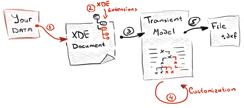 |
Customized data translation workflow. |
Let's comment a bit on what is depicted above. We start off by composing the XDE document and populating it with the standard and custom attributes (steps 1-2). Once the document is ready, we ask the native OCC translator to compose what is called a "transient model" (step 3). This transient model is the in-memory representation of the DXF document (a side note: the same applies to STEP, IGES, and other formats) that stores all DXF entities as objects together with the relationships between them. The data conversion to a transient model is usually implemented in the Transfer() method of a translator, regardless of whether it's based on XDE or not. Once we have a transient model, we have to reflect there all the customizations we made for the original XDE document (step 4). The latter is achieved by working with the transient model's API and adding some more entities there (e.g., linetypes). Here's a code excerpt for a function that accepts an XDE document, reads a newly added linetype attribute, and adds it to the transient model:
bool WriteLinetypes(const Handle(TDocStd_Document)& doc)
{
  Handle(DxfSection_Model)
    dxfModel = Handle(DxfSection_Model)::DownCast( WS()->Model() );

  // Find the DXF layer entity to fill with the data from OCAF.
  Handle(DxfSection_Layer)
    layer = dxfModel->FindLayer("FOLD_LINES");

  Handle(XCAFDoc_LayerTool)
    layerTool = XCAFDoc_DocumentTool::LayerTool( doc->Main() );

  // Find the linetype attribute.
  TDF_Label                       bendsLayerLab = layerTool->FindLayer("FOLD_LINES");
  Handle(fraAlgo_DxfLinetypeAttr) linetypeAttr;

  if ( !bendsLayerLab.FindAttribute(DxfLinetypeAttr::GUID(), linetypeAttr) )
    return false;

  // Get linetype entity.
  const Handle(DxfSection_LType)& ltype = linetypeAttr->GetLinetype();

  // Pass linetype to the layer.
  layer->SetLineType( ltype->GetName() );

  // Find a table with linetypes.
  Handle(DxfSection_Table) ltypesTbl = dxfModel->FindTable("LTYPE", false);

  // Add linetype to the LTYPE table.
  Handle(DxfSection_HSequenceOfObject) objects = ltypesTbl->GetObjects();
  objects->Append(ltype);
  ltypesTbl->SetObjects(objects);

  // Add entity, so that AssignHandles() can iterate the model
  // to put unique identifiers (handles) for each entity, including
  // the newly constructed linetype.
  dxfModel->AddEntity(ltype);

  return true;
}
Ideally, steps 3 and 4 should be united into a somewhat enhanced translator, so that it's the job of the translator to compose the transient model right away, and no post-processing is needed. The final stage (step 5) is to serialize the transient model to the filesystem. This is where no customization is usually done.
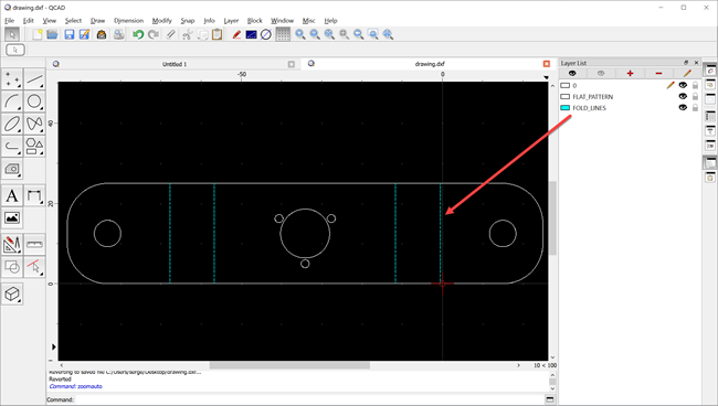 |
A drawing with custom linetypes on a separate layer. |
Wrapping up
XDE framework is a workhorse for traditional file-based data exchange scenarios. The practice proves that it performs nicely although it's kinda poorly documented and sometimes not easy to manipulate. The good news is that it's already plugged into all OCC data translators, both open-sourced and commercial. Moreover, even 3-rd party vendors, such as CAD Exchanger, keep this XDE gate open for seamless integration with OpenCascade. Unlike other vendor-specific binary formats, XDE is open and is not quite specialized for any data format or the data model of the OpenCascade kernel itself. Actually, it is still evolving and new sections are being added to the XDE storage schema with the new releases of the library. What especially warms the soul is that this format is both forward and backward compatible.
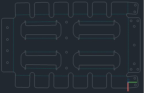 |
Another drawing with custom linetypes on a separate layer. |
Having said the above, there's one remark to add about the generality of the XDE framework. If you're looking for flexibility, it is still better to start with the bare OCAF and compose your own storage schema capturing your domain data. Where XDE really shines is the data exchange scenarios.
Update from 10.08.2022: This article was also published by OCC in their official blog. Hopefully, that would help to spread a word about our lovely OpenCascade and some intricate ways of its usage.
Want to discuss this? Jump in to our forum.