On sheet metal unfolding (Part 3)
Mastering k-factor
In Part 2, we discussed how to unfold cylindrical bends precisely. However, praxis puts additional constraints to respect in order to get precise unfolding. During sheet metal bending, the inner surface of the bend compresses while the outer one stretches. Therefore, somewhere in between, there is a zone separating the tension from the compression. In this zone (called "neutral axis"), the material gets zero distortion. When looking at the folded state of a sheet metal part we view the deformed flat pattern's shape. The following question arises then: which dimensions of a flat pattern produce that folded shape?
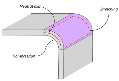 |
Bend compression and stretching. |
For precise flattening, we have used a simple formula BA = R*angle, where BA stands for "bend allowance," R is the cylinder radius, and "angle" is the cylindrical sector's angle. That's simply the arc length if applied to a circle. The following observations aim at taking into account the physical side of the issue:
- A sheet metal bend is a pair of cylinders, not just one cylinder.
- Both cylinders are separated by constant-thickness material.
- There is a particular radius value RN where material neither compresses nor stretches.
Therefore, bend allowance is BA = RN*angle, and the question now is how to compute RN.
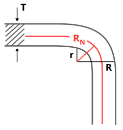 |
RN is somewhere in the middle. |
Sheet metal manufacturing employs an empiric k-factor value to compute flat pattern's dimensions. This factor specifies the relative offset to take from the inner bend's face to the neutral axis. Therefore, RN = r + k*T, where r is the inner bend's radius, and T is the material thickness. The k-factor here is simply a multiplier that allows us to locate the repositioned neutral axis after forming. Read more about k-factor in The Fabricator magazine. What is important to grasp here is that k-factor is, generally speaking, not a constant value. As the neutral axis' position depends on the bend angle, inside bend radius, and forming method, the k-factor is a function of these things. E.g., the smaller the inside bend radius, the more the neutral axis will shift toward the inside surface of the bend.
 |
Unfolding a cylindrical face with different k-factors ranging between 0 and 1 (normally the k-factor value does not exceed 0.5). The thickness value was forced to be 1 here (for the k-factor to affect the unfolding result). |
The neutral axis is positioned in the middle of the material in its flat state. On bending, the neutral axis starts moving towards the inner bend. The movement percentage is actually the k-factor, whose value begins from 0.5 and only decreases on bending as the compressive stress can never exceed the outer tension.
 |
Flat pattern of a sheet metal plane. |
From the geometry point of view, applying k-factor is not rocket science. We only have to change the scaling rule we used for the U-coordinate distortion and assure that the caller code provides the material definition (e.g., in the form of a table with coefficients).
Anomalies
Among thousands of sheet metal parts I have ever seen, quite a significant number was poorly designed. Some parts were impossible to manufacture as their flat patterns were self-overlapping. Some others were not conventional, e.g., they had a variable thickness, which is not allowed for traditional sheet metals. Quite a few cases suffered from mismatching bends, e.g., the outer surface's radius was smaller than the inner one. The favorite algorithmic answer to such anomalies is the error message or, even worse, an exception raised (that is too bad). But, there's still something good you can do about such bad cases:
- Skip bends that cannot be unwrapped. It is better to have a gap in the flat pattern than not to have a flat pattern at all. A couple of missing bends still enable estimation of the stock dimensions so that such flat patterns can be useful for manufacturing planning.
- If the bend surfaces mismatch, it is still possible to derive the inner and outer radii using one available radius and thickness. E.g., if a bend is concave, then it is the inner one. To obtain the outer radius, one can simply add the thickness value to the known inner radius.
- Use warnings whenever possible. Ask yourself if the problem you are facing with the dirty data is really so critical that you cannot produce any valuable outcome. Should the algorithm halt because of a small local anomaly?
Want to discuss this? Jump in to our forum.