On sheet metal unfolding (Part 5)
Preamble
This article continues the "Unfolding" series aimed at describing our algorithm for flattening sheet metal parts. We began working on these algorithms back in 2017 and have accumulated quite a bit of knowledge since then. Here is a brief recap of what was discussed in the previous "episodes":
- Part 1 gives an introduction to unfolding and reviews the software packages solving similar tasks.
- Part 2 explains how bends can be unrolled precisely.
- Part 3 instructs how to survive the K-factor.
- Part 4 outlines the structure of the unfolding algorithm. It also introduces the notions of "unfolding tree" and the "border trihedron" that are essential ingredients of the solution.
Here is Part 5 of our "Unfolding" story that keeps unfolding over the years. It is devoted to a specific type of sheet metal part that requires rolling. We set aside other types of sheet metal that are fairly similar, such as profiles or tubes. Their time will come.
In this article, we revisit some of the fundamental concepts introduced in Part 4 and present an alternative approach to unfolding. The new method is more general and is suitable for any geometries whose faces can be flattened down onto a drawing plane.
Rolling versus bending
There is one particularly interesting case to handle in the unfolding algorithm: when a part in question is to be rolled and not only folded on a press brake machine. Roll bending becomes a thing in several situations, e.g., when a part does not contain any planar flanges or when the "bending" radii are too large (e.g., 25-40 millimeters). In the latter case, it's not bending anymore because a press brake machine is incapable of making large cylinders.
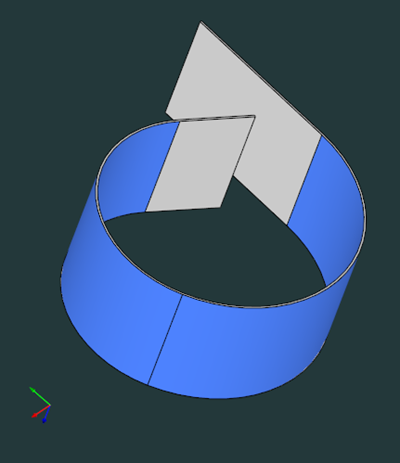 |
Fig. 1. Consecutive "bends" forming a rolled feature (blue). |
In CAD geometry, rolling is often explicit due to the very arrangement of cylindrical faces. There are the following topological hints that might indicate roll bending in a sheet metal part:
- P1: Two "bends" of different radii coexist next to each other (Fig. 1).
- P2: There is a dangling "bend" not followed by any planar flange (Fig. 2).
In both cases, what is missing is a planar support face that would allow press-braking the part. So in both these cases, the corresponding cylindrical "bends" are not actually bends as such, because no folding is going to happen there. These are rather the "rolled flanges" or whatever name you prefer to call them.
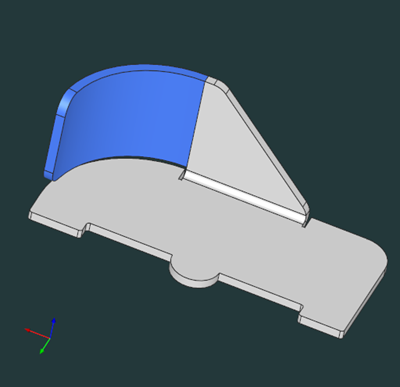 |
Fig. 2. One example of a dangling rolled flange (blue). |
If you hand a rolled part to an experienced engineer, he will likely immediately tell you if it's really a rolled or folded one. Aside from the topological hints mentioned above, there's also geometric reasoning, e.g., the max allowed bend radius.
For example, discovering large enough bend radii might be sufficient to conclude that a part is rolled. In contrast, having small consecutive bends is likely just a bad design. There could be uncertain cases, e.g., when a series of consecutive bends terminates with no flange. After reflecting a bit on that matter, one might compose the following kind of informal checklist (Fig. 3):
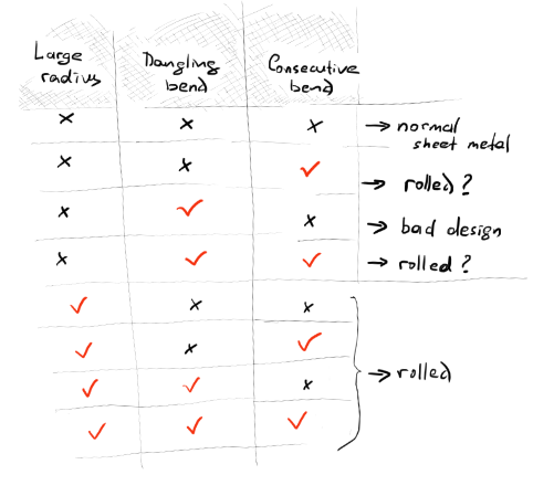 |
Fig. 3. Possible classification based on geometric and topological analysis at bends. |
What's wrong with the unfolding?
In Part 4, we introduced the unfolding algorithm that was supposed to work on classical sheet metals, where a planar flange is king, whilst a bend face is a somewhat virtual feature.
As we saw before, unfolding starts by populating a transformation tree (Fig. 4). The tree nodes are the planar flanges, and the links represent parent-to-child relationships. Each secondary flange stores the collection of bends and the local flattening transformation.
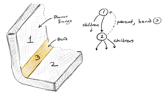 |
Fig. 4. A fragment of an unfolding tree for a sample case. |
This unfolding algorithm was essentially aware of feature kinds and production methods, so it was not purely geometric. Here's a little story about it.
Back in 2017, we got a project from one famous company doing lots of sheet metal manufacturing. The challenge was kinda typical: to help the sales engineers with fabrication cost estimation. Feature recognition and unfolding tools were supposed to answer the following routine questions:
- How many holes and cutouts does the sheet metal part have?
- What are the blank sheet dimensions prior to bending?
- How many bend operations are required to get the folded state of the part?
- Are there any non-cutting features that require specific tooling?
- Are there any flaws in the initial design?
- etc.
A "canonical" sheet metal part is a computationally convenient thing. Indeed, the majority of sheet metal parts are composed of mating planes, whereas all deformations are centered at cylindrical bends. We were not looking for a precise unfolding solution back then, so our approach was as simple as ABC:
- Go over all planar sheets starting from the reference one, and compose a relationship tree between planes.
- Using the already known bend angles and bend compensations, flatten all flanges by rotating around the bend lines and translating by the distances of bend compensations.
- Fill gaps between the flattened flanges to represent the unrolled bends.
Our approach was heavily influenced by the article [See Toh, K.H. et al (1995). A feature-based flat pattern development system for sheet metal parts] published in the Journal of Materials Processing Technology. This old paper describes a flat patterning technique that runs on AutoCAD. The key benefit of this algorithm is its inherent simplicity. The process of flattening is essentially reduced to a combination of rotations and translations, so it's nothing but paving your faces one after another in the assumption that all gaps between the flattened flanges can be filled later on (Fig. 5).
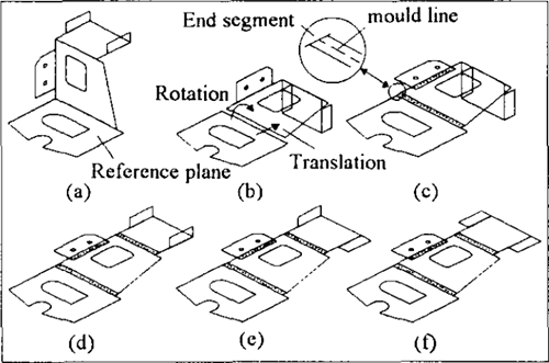 |
Fig. 5. Rotation-based unfolding with line segments for connecting bends (illustration from the paper by K.H. See Toh et al). |
In our implementation, gap filling was extremely simple: we just connected the consecutive flanges with trapezium. This method gave a suitable level of approximation for the blank sheet dimensions, despite the loss of accuracy brought on by such idealization. The next logical step was to make gap filling precise to get accurate cutting contours. And that's exactly what we discussed in Part 2.
If implemented properly, rotation-based unfolding is speedy, robust, and accurate. But as experience shows, it has certain fatal weaknesses.
How about rolling?
The biggest problem with the rotation-based unfolding is its inability to handle rolled parts. Simply put, the gap filling stage is useless for non-canonical sheets since they might have no planar flanges at all. The presence of rolled faces makes this whole thing a bit under-engineered. In a rolled part, it can easily happen that one cylindrical surface is followed by another cylinder, and so it goes with no particular order.
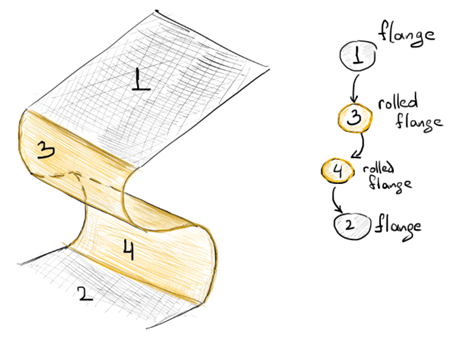 |
Fig. 6. A specific "rolled flange" node in the unfolding tree (a dead end attempt to fix unfolding tree). |
One may try to handle this situation by declaring all cylinders as specific "rolled flanges" and tweaking the unfolding tree to accommodate them (Fig. 6). However, as practice proves, that's a dead end track. Some questions would arise right away if you tried to "enhance" the rotation-based unfolder to treat rolled features:
- What if a part does not contain any planar sheets? The rotation-based unfolding is simply out of touch in that case as its whole unfolding tree is plane-centered.
- How to distinguish between "bends" and "rolled flanges" if the only difference between them is potentially their radii? Do we want unfolding to perform a somewhat feature (sub)recognition?
All this does not seem like a minor issue that can be fixed quickly. Even if we manage to tweak the rotation-based unfolding to accommodate the consecutive rolled faces, what kind of an algorithm is it going to become at the end? Would it be even maintainable?
Repeated computation of bend allowances
Another problem is less obvious and is related to the accuracy of bend unrolling. All flanges are intended to be flattened simultaneously at their final locations by the rotation-driven unfolding. In order to do so, the algorithm calculates the theoretical bend compensations and ensures that the flat flanges are offset at the proper lengths (Fig. 5b).
However, at a later stage, gap filling comes into play. It has to lay the unrolled bends exactly into the reserved vacant areas, and that is not so easy as long as we unroll precisely. The problem here is the approximate nature of bend unrolling. Much like any other approximation algorithm, bend unrolling comes with its own (im)precision. What really happens is that we compute bend compensation twice: once to move flanges apart, and the second time to unroll a cylinder with the K-factor scaling. It would be quite difficult to shuffle the flattened flanges during gap filling because their positions are interdependent. Ideally, we would need to make sure that bend compensation is computed only once. Here we must put into practice that golden principle of geometric computation: "don't do the same calculation more than once."
Is your flat pattern flat?
This one is probably the funniest flaw of the rotation-based unfolding. The thing here is that bend angles are floating-point numbers, and hence they can suffer from round-off errors. Moreover, the bend angle computation as such might be another source of inaccuracy. Although in the vast majority of cases you'd never see any planarity defects, the very fact that each individual flange is rotated independently does not make your flat pattern ideally flat. In the micro scale, it might remain foldy and yield small angular deviations between the normal vectors of the flattened flanges.
Solution: unfolding revisited
A completely alternative approach to unfolding is designed to overcome the limitations of the legacy one. We figured out the following guidelines for implementing the revisited algorithm:
- Avoid gap filling.
- The order of planes and cylinders in the model should make no difference for unfolding.
Given that we understand how to unroll each individual face, the second condition would allow us to unfold literally any sheet metal part. The unfolding process should potentially accommodate new types of geometry, including cones and whatever kinds of developable surfaces. It would even be possible to unfold intrinsically curved (non-developable) splines because the new algorithm does not care about geometry types anymore. What it does care about is providing a topological framework, so that each consecutive CAD face is attached to the previous one. Of course, adding other types of geometry would require implementing the corresponding numerical methods, which may even need to take into account deformations. Still, such methods are supposed to be implemented separately from the main unfolding routine. But let's set aside the topic of non-developable surfaces for the time being. We may revisit it later.
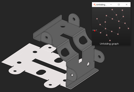 |
Fig. 7. A sheet metal part with a rolled flange unfolded with the new algorithm. |
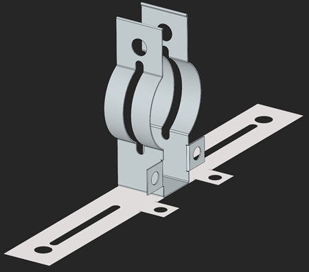 |
Fig. 8. Another example of part with rolled flanges. |
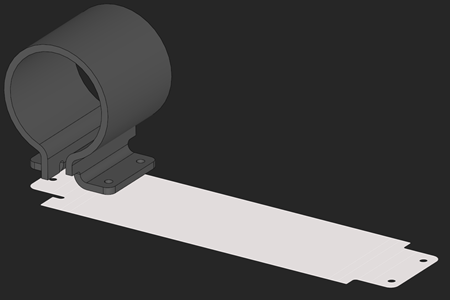 |
Fig. 9. Pipe holder. |
In the new approach, an unfolding graph does no longer degenerate into a tree (Fig. 7). Actually, this isn't the key thing, because a tree would work here equally well. We deliberately keep the graph data structure to be able to trace all adjacency relationships between all flanges being unrolled (and this can help in assessing feasibility, as we'll see later). When it comes to actual flattening, all the graph nodes are visited only once for unrolling. Figures 7-9 above illustrate some cases that couldn't be handled by a rotation-based unfolder, although they are nothing special for the revisited one.
The unfolding graph we use here is similar to AAG. One difference is that it has a specific "root" node that defines the reference plane for flattening all other faces down to that plane. Unlike the unfolding tree we used before, this graph does not treat bends specifically. All faces are just regular nodes, and we don't have to worry about their "mechanical" role, whether it is bending, rolling or whatever else. What is necessary, though, is to know how the unrolled faces are attached to each other. Since we do not take into account any bend angles here, we need something else to pave flat shapes near each other. This is something we call an "anchor point."
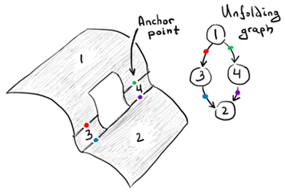 |
Fig. 10. Anchor points. |
An anchor point is actually a common edge between two folded faces that's going to produce two images on the consecutive unrolled faces. This anchor point is associated with a graph link connecting two faces that should be aware of each other (Fig. 10). Once unfolded, we compute a translation (and possibly flip transformation) using the border trihedrons (see their definition here) evaluated on the unrolled images of the anchor edge (Fig. 11).
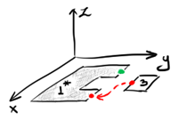 |
Fig. 11. Two images of consecutive faces are attached using the anchor points. |
The unrolled representation of geometry is stored right in the graph nodes to be easily accessible at the flat pattern construction stage (Fig. 12).
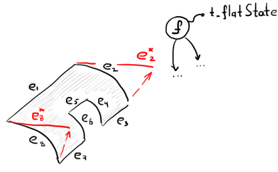 |
Fig. 12. Unrolled edges are stored in the "history" together with the flat representation of their owner face. |
The new algorithm is not only simpler but also has fewer requirements for prior feature detection. We no longer need to know bend angles, and the only thing that reminds us of sheet metal here is the need to calculate the K-factor at bends. The latter is unavoidable because we need to apply a certain deformation scaling to remain physically correct. Still, detaching the recognition logic from the unfolder makes it possible to let the user just select a set of faces he wants to unfold and let the magic happen (Fig. 13). Independence from feature recognition makes the new unfolding similar to the UnrollSrf command in Rhino.
 |
Fig. 13. Unfolding is independent from feature recognition. |
Feasibility
What's written above is perhaps the most intuitive way of unfolding. Indeed, why wouldn't you just unroll each face separately and stitch the flat shapes together? This whole story is a good lesson in how easy it is to go down the wrong path if you oversimplify things and choose overly idealistic algorithms. Still, there are some issues to address even with the new enhanced algorithm.
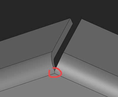 |
Fig. 14. Invalid configuration of bends. |
The biggest challenge for the algorithm is how to deal with poorly designed parts. It's not uncommon for a sheet metal model to contain a somewhat inconsistent configuration of bends. For example, if one bend face is topologically glued to another bend face (Fig. 14), the corresponding unfolding graph will contain an excessive number of adjacency connections that can throw the unfolding process into ambiguity. To cure this problem, we would have to exclude the conflicting neighbors from visiting by cutting them out of the graph. Such a solution would require additional feature-based reasoning.
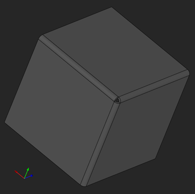 |
Fig. 15. Infeasible part. |
Using the true graph data structure (instead of a tree) can also bear some further fruit. If we know that an unrolled surface is reachable from several parent faces, we can compare the flat shapes generated by all variants. We expect that the flattening results are identical no matter which path we take in the unfolding graph. A constructive discovery here is that this symmetry does not hold for certain infeasible parts (Fig. 15), nor for tubes. Implementing such checks is a straightforward method of feasibility assessment for a sheet metal part.
Some further validation can be done on the flat pattern itself. This includes checking for overlapping flanges and missing bend reliefs. The result of a good unfolding algorithm is therefore not just a pure geometric artifact. It is more like a volume of knowledge that we managed to extract from the input design, including its features and problematic spots.
Want to discuss this? Jump in to our forum.