On sheet metal unfolding. Part 7: drilled holes
- Part 1 gives an introduction to unfolding and reviews the software packages for solving similar tasks.
- Part 2 explains how bends can be unrolled precisely.
- Part 3 instructs how to survive the K-factor.
- Part 4 outlines the structure of the unfolding algorithm. It also introduces the notions of the "unfolding tree" and the "border trihedron" which are essential ingredients of the solution.
- Part 5 introduces a generalized unfolding algorithm that can handle rolled parts and parts with specific design issues, such as terminating or consecutive bends.
- Part 6 is the introduction to another challenging problem of sheet metal processing, which is bend sequence simulation.
Preamble
It should not come as a surprise to a careful reader that our unfolding algorithm operates on a single side of a two-sided model. As a result of recognition, we are able to separate the "outer" sheet faces from the "inner" sheet faces, and this way we can idealize a solid workpiece into a two-dimensional shell. After that, one of the obtained shells is chosen for further unfolding, while the other is simply ignored. However, this method has an inherent flaw in that two sheets are not always identical.
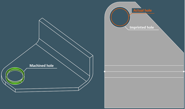 |
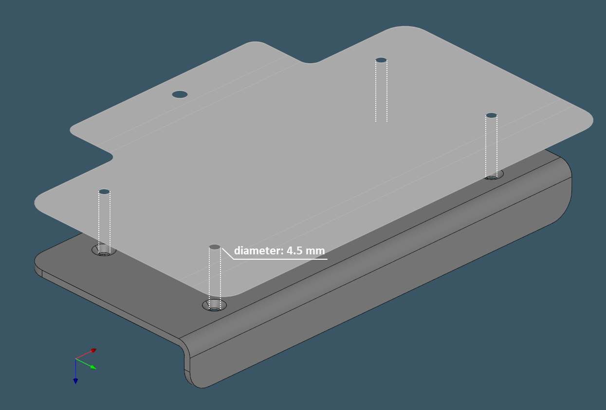
Double-sided countersunk hole and its contour, which appears to be incorrectly mapped to the flat pattern. |
The presence of machining features, such as counterbored or countersunk holes, cannot be ignored if we want to obtain an accurate flat pattern at the end. In the corresponding technical drawing, we should be able to depict the hole's main diameter, which is not captured by the unfolder.
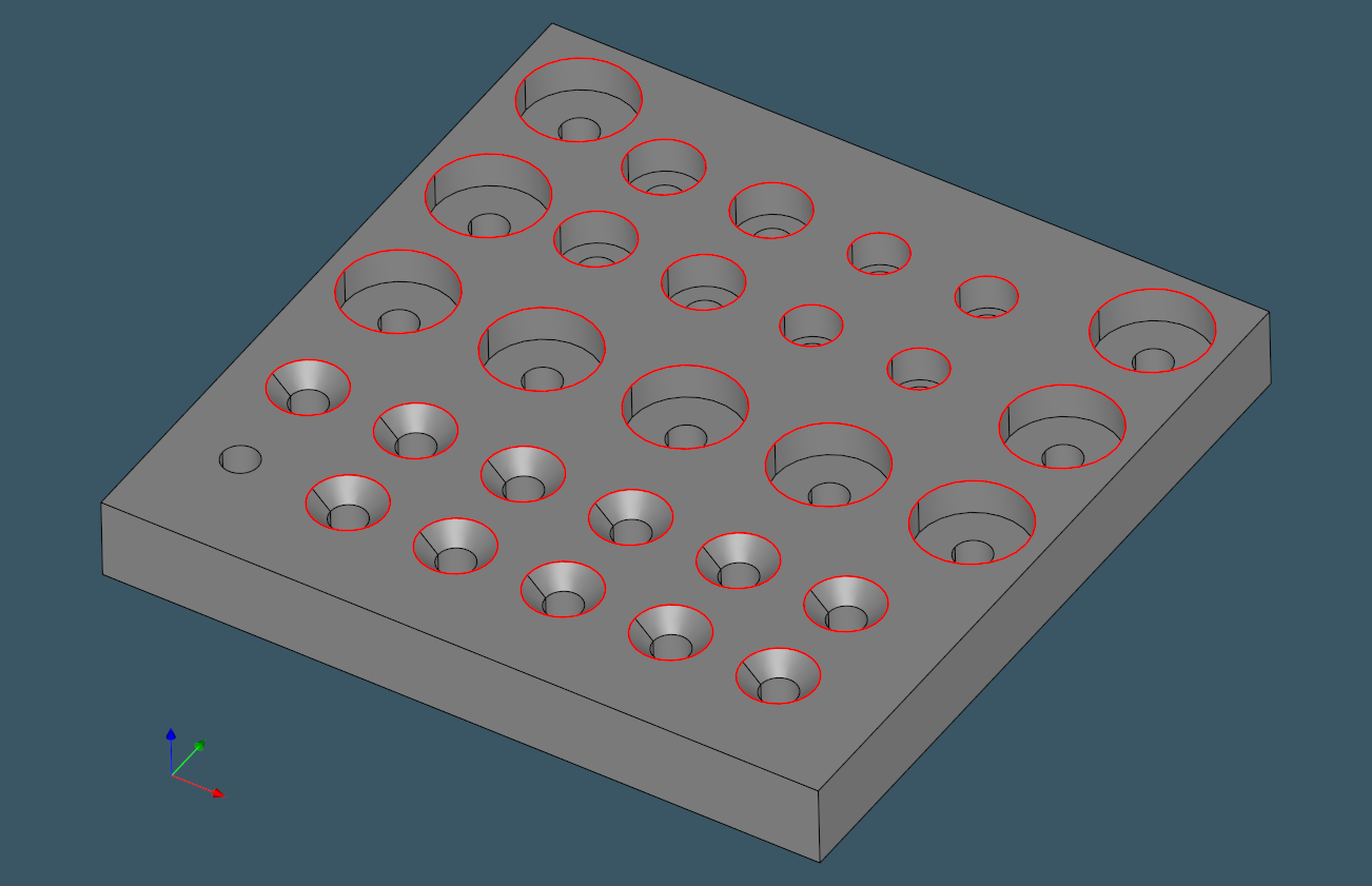 |
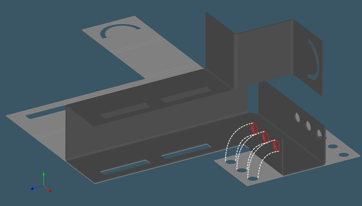
Insertion contours of machined holes on a plate part. |
Machined holes are common, but they are not the only form of feature where laser cutting is insufficient. Fillets and chamfers over sheet metal edges are two other machining features that are frequently encountered. These features are sometimes modeled on top of an otherwise valid sheet part to simulate edge deburring. We leave out fillets and chamfers from the scope of this discussion since we consider that such features should not be present in an appropriate sheet metal part (with some exceptions which will be discussed later in this series).
Approaches
There is nothing to do if a hole is plain because any sheet metal side (lower or upper) completely captures its contours. The situation gets worse when holes are drilled with countersinks or counterbores or when explicit edge machining is required. Several techniques for dealing with such situations rapidly come to mind:
- Defeature complex machined holes from the 3D model and insert plain ones instead.
- Adjust the flat pattern of the part to compensate for the diameters of countersinks and counterbores.
- Unfold both sides of a part and fuse the obtained flat patterns.
The first solution is simple, but it does not work well with the computational architecture we have. Here's why. When a part is identified as sheet metal, its associated AAG is powered with the relevant attributes. As pointed out earlier, AAG always reflects a "frozen" state of geometry, which means that any changes to the model will basically invalidate the graph. As a result, once a model is defeatured, the feature attributes on the associated faces are lost, and the model cannot be transmitted to the unfolder. This can be seen as a limitation of our AAG implementation, yet it can be worked around. Using the modification history, one can either edit the AAG (which we do not allow) or derive another AAG with inherited attributes and updated face indexation.
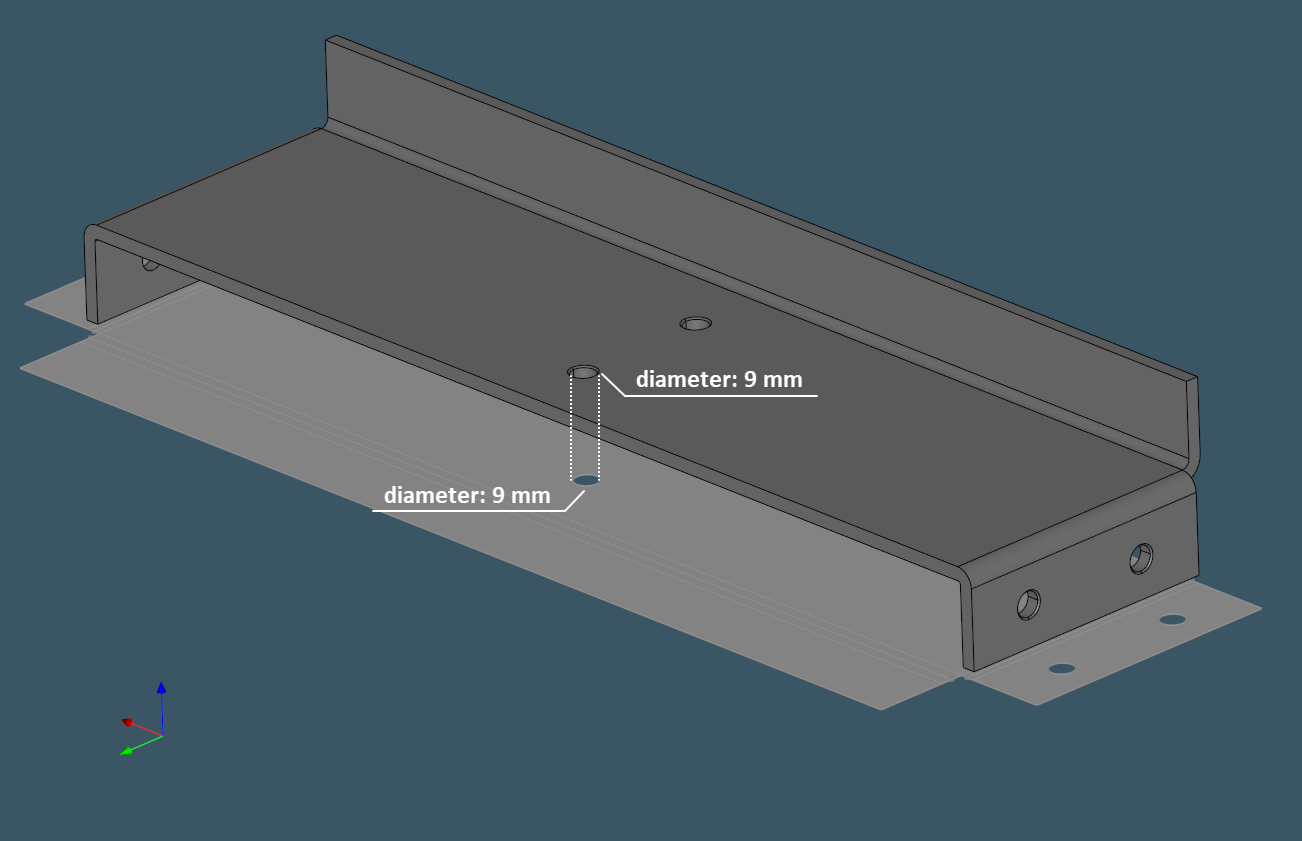 |
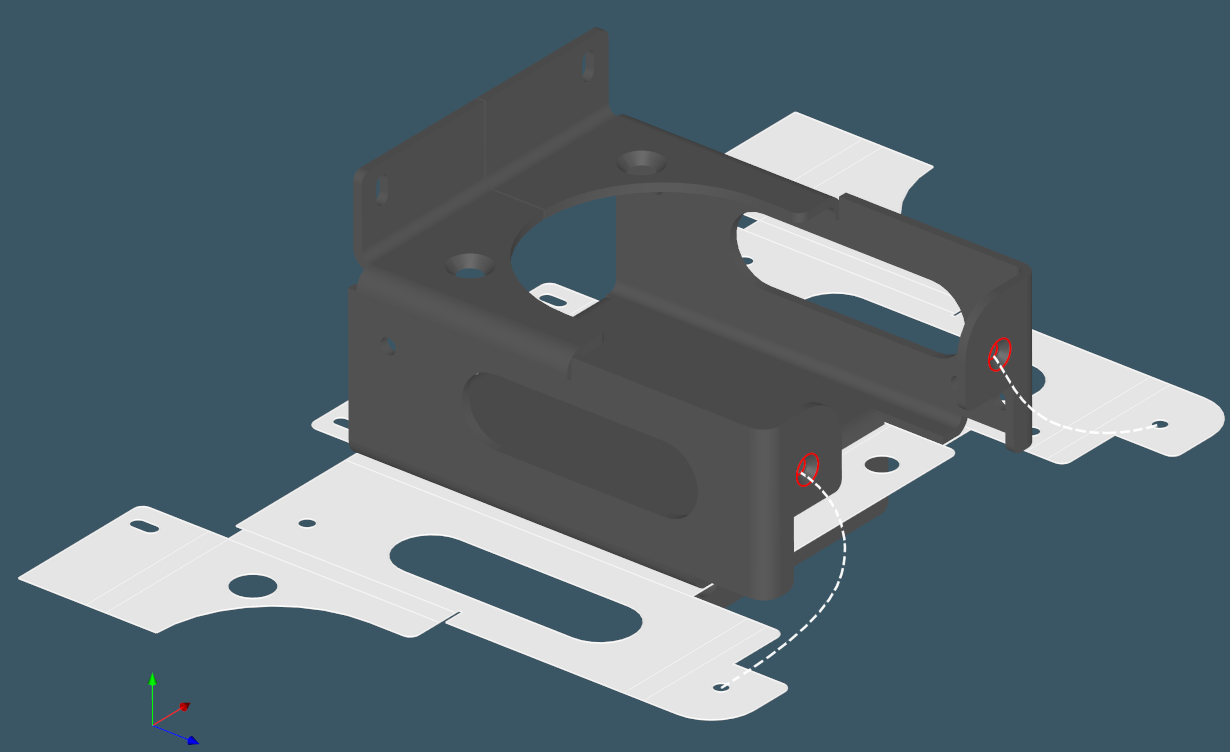
The diameter on the flat shape should be the same, and that is not given for granted. |
The second option is to let the unfolder do what it does and rather post-process the resulting flat pattern. Another variation of the same approach is to modify the insertion contours right in the unfolding algorithm. We must be able to keep track of hole contours in order to know which contour on the flat shape corresponds to which hole once the part is unfolded. The third option would allow to handle single-sided countersunk and counterbored holes, although it would stay powerless if a hole is machined from both ends.
 |
Change hole diameters on a face. |
We chose to keep things simple while remaining structurally connected to the existing recognition framework. To begin, all machined holes are identified, and their insertion contours to the base faces get stored as AAG attributes of the respective faces. Later, when asked to build an image for a planar flange, the unfolder checks for the presence of these specific attributes and reinserts the contours with appropriate diameters. For the reinsertion mechanics, we use the "topological killer" tool, which recomposes the affected shapes top-down.
 |
 |
 |
This simple "reinsertion" technique allows us to generate precise technical drawings in which each machined hole receives a contour with the correct diameter, regardless of how many countersinks or counterbores it had. The feature recognition tool reports information about the hole type and its more detailed properties. Such information has no direct relationship to the unfolder, so the mechanics of recognition remains divided from the flattening algorithm.
Yet, as already mentioned, complex holes are not the only kind of feature that dictates extra machining over a laser-cut item. The presence of such features can be exceptionally troublesome in sheet metal automation processes, and there are occasions when there is no better option than simply alerting a human operator that a part is just "badly" designed.
Want to discuss this? Jump in to our forum.