Point to bounding box directional distance
One smart guy told me that a manufacturing plan should always be questioned, even when it is composed by a pretty respectable software package, whatever it is, Mastercam or Fusion360, you name it. If what you're doing is, for example, fabrication cost estimation, it's always an approximation: coarser or finer, but never absolutely precise. Today, let's discuss yet another sketchy idea of extracting manufacturing information for a CAD model. The essence of this idea is to substitute feature recognition with intensive ray castings. Before going too deep with all this, here is a precaution remark: I don't know which approach for extracting machining props is better. All automated methods require a great deal of calibration to better fit the production reality. So what's given below is more like food for the mind.
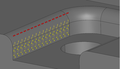 |
Distance to AABB at random probe points on a single face. |
The ultimate manufacturing price is a function of several variables, many of whose are geometric in nature. For example, to assess manufacturability of a single face or a feature, it is necessary to predict how a tool is going to approach it. To approximate the tool length and diameter with respect to a CAD face, the following simple technique can be used. Let's cover our face with a "dense enough" point distribution and measure two values at each probe: clearance and depth. Clearance is the distance from a probe point on a face to any other feature next to it in the face normal direction. This value has direct relation to the max allowed tool diameter. Depth is the distance from a probe point to the stock boundary (e.g., a solid box) measured in the a priori known machining direction. This depth value is evidently related to the tool length.
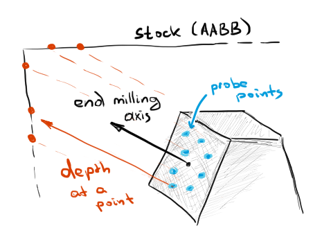 |
Depth at a point w.r.t. the machining direction. |
While both clearance and depth values are easily computed with a ray-casting method, there is one essential unknown in this whole approach. What are the machining directions? Well, actually, these directions can be guessed heuristically based on feature recognition. But let's leave this subject aside for now as it is a big topic in itself.
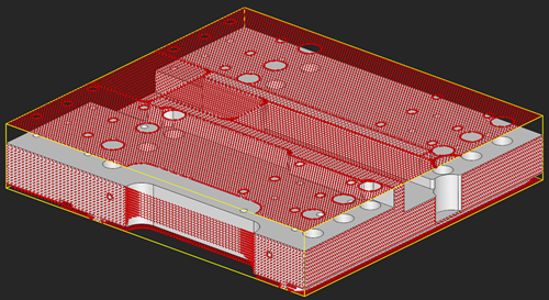 |
Bounding box of a part is covered by depth measures for all feature faces. |
If we manage to associate depth/clearance scalars and the machining direction field with each point on a CAD face, the resulting data structure will already serve as a somewhat approximation medium to the manufacturing plan. The values of depth, clearance, and machining directions can potentially tell more about features than, for example, primitive voxel nodes or dexels. It is still a question though, how to utilize this data effectively, because without a clear recipe this whole discussion isn't worth a penny. Still, the idea looks quite promising. For each CAD face, we extract not only its local properties, such as a surface type, curvature, area, etc., but also its global properties with respect to the other model regions. Here we step aside from the feature recognition as such, and keep ourselves focused on individual faces that become aware of features indirectly, through intensive ray scanning.
Now, to the dirty practice. To measure depth values for a selected face, Analysis Situs 1.2 (the upcoming release) will provide a specific Tcl function:
Checking the distance from a point to the axis-aligned bounding box (AABB) in a predefined direction is a standard algorithm. I borrowed the implementation 5.3.3 from "Real-Time Collision Detection" by Christer Ericson and it worked nicely. Here's the code:
int RTCD::IntersectRayAABB(Point p, Vector d, AABB a, double &tmin, double &tmax)
{
  const double EPSILON = RealEpsilon();

  tmin = -DBL_MAX; // set to -DBL_MAX to get first hit on line.
  tmax = DBL_MAX; // set to max distance ray can travel (for segment).

  // For all three slabs
  for ( int i = 0; i < 3; ++i )
  {
    if ( Abs(d[i]) < EPSILON )
    {
      // Ray is parallel to slab. No hit if origin not within slab.
      if ( p[i] < a.min[i] || p[i] > a.max[i] )
        return 0;
    }
    else
    {
      // Compute intersection `t` value of ray with near and far plane of slab.
      double ood = 1.0f / d[i];
      double t1 = (a.min[i] - p[i]) * ood;
      double t2 = (a.max[i] - p[i]) * ood;

      // Make `t1` be intersection with near plane, `t2` with far plane.
      if ( t1 > t2 )
        std::swap(t1, t2);

      // Compute the intersection of slab intersection intervals.
      tmin = Max(tmin, t1);
      tmax = Min(tmax, t2);

      // Exit with no collision as soon as slab intersection becomes empty.
      if ( tmin > tmax )
        return 0;
    }
  }

  // Ray intersects all 3 slabs. Return `tmin` and `tmax`.
  return 1;
}
Once we know the probe point `p`, the machining axis `d`, and the stock box `a`, we can easily compute the "depth" property at the point `p` through the stock. Supplemented with the clearance value, this depth serves as an idealized tool descriptor. Knowing the tool props, we can match it with the available tooling in a machine shop to see if a specific face can be fabricated. The next stage would be to estimate fabrication costs, but here we're entering into a somewhat non-geometric area, and I'll better leave that discussion to technologists.
I was thinking how to conclude this small blog post, but nothing actually comes to my mind. That's likely because what's written above is more of an open question. At the same time, this crumpled discussion opens the door to another challenging niche: Design for Manufacturing (DfM). Let this post be a teaser for the new "DfM" rubric then.
Want to discuss this? Jump in to our forum.