Point to convex hull directional distance
One smart guy told me that the directional distance to a bounding box (i.e., a stock shape) is not as fun as the directional distance to the convex hull. Having convex hull as a virtual stock offers yet another approximation for pointwise depth of a feature. Whether convex hull is "better" than a bounding box is possibly an open question, but the motivation of using convex hulls is quite clear: with convex hulls as stocks, we tend to not overestimate tool lengths required for machining.
RTCD by Ericson
Computationally speaking, we need an efficient algorithm to intersect a ray with a convex hull. For that purpose, we are going to use another approach from the "Real-Time Collision Detection" monograph by Christer Ericson. In the sec. 3.6, Ericson proposes a "constant-normal" form of a plane data structure, which we added to the RTCD namespace of Analysis Situs with the following properties:
struct Plane
{
  Vector              n;      // Plane normal. Points `x` on the plane satisfy `Dot(n,x) = d`.
  double              d;      // `d = dot(n,p)` for a given point `p` on the plane.
  tl::optional<Point> anchor; // Optional anchor point.
};
The optional "anchor point" is computed externally as a visual "docking" location of the plane. Since planes are infinite, we need to be able to visualize them in a reasonably clean way, so this anchor point is nothing but the origin point from where a plane starts its infinite expansion. Introducing this extra property does not change anything in the Ericson's math.
 |
Constructing plane for each facet of a convex hull. |
Constructing planes for every facet of a convex hull gives a set of halfspaces to be used in the computation later on:
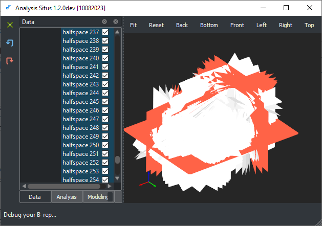 |
Halfspace planes for all facets of a convex hull demonstrated above (different colors are used for front and back side of a plane). |
The sec. 5.3.8 of the Ericson's book comes with an algorithm to intersect a ray against a convex polyhedron. The polyhedron is specified as an array of planes. The idea is quite simple yet elegant: let's clip the passed inspection ray with all halfspaces one after another until we iterate them all and obtain two parameters on a ray (min and max).
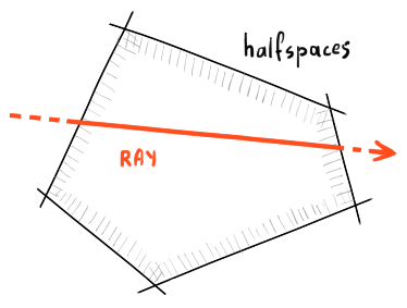 |
Ray clipping. |
To run this algorithm in Analysis Situs (starting from ver. 1.2), use the following command:
With no arguments passed, this command will measure the distances for all selected faces of an active part. It should be noted that this command is intended for test use only as in the production code you would certainly prefer precomputing the convex hull once and passing it in the computation whenever required.
 |
Distance to convex hull from selected faces. |
There is one little note to be added regarding the complexity of convex hulls. Analysis Situs comes with an algorithm named asiAlgo_BuildConvexHull that constructs the convex polyhedron as a mesh based on the facets supplied within the analyzed body (in OpenCascade, facets are distributed by faces). The complexity of the hull is dependent on the input mesh density, so the mesh representation of a convex hull is not unique. Here is one example:
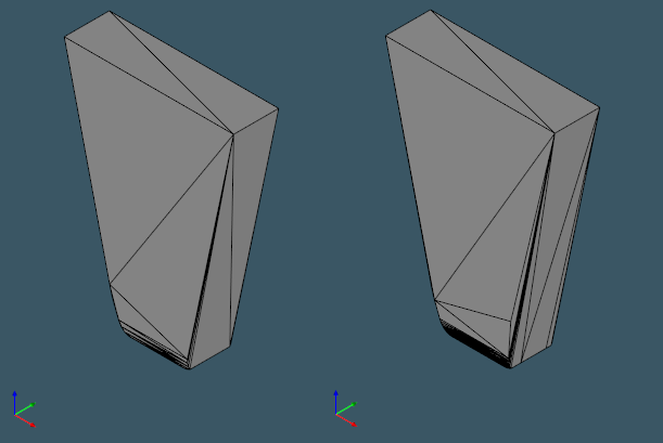 |
Not all hulls are equal. |
To reduce the number of employed halfspaces and decrease the computational burden, it looks reasonable to decimate a convex hull stock prior to ray clipping.
 |
Decimation of a convex hull mesh. |
BVH-based distance computation
It is probably not that obvious that the halfspace-based algorithm possesses a severe deficiency. The issue with this technique is that it is quite sensitive to the halfspace plane orientations. A minor error in the convex hull triangulation is sufficient to invalidate the entire computation. Worse, any local "dirtiness" in a model, such as a tiny flipped triangle, will have global impact on the classification outcome. Indeed, such a triangle (small or large) becomes a fair halfspace that messes everything up, regardless of how "small" its used portion was.
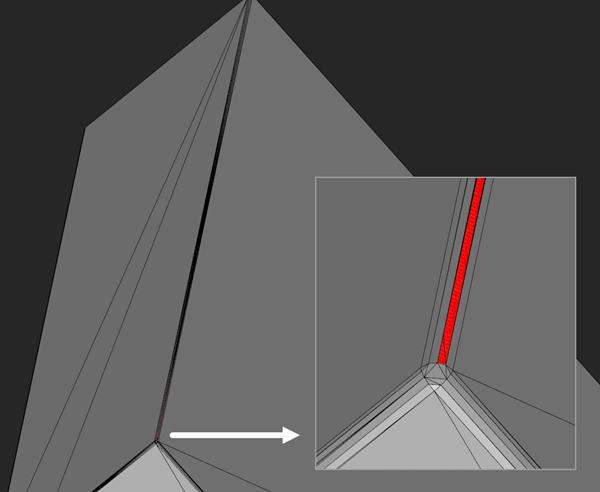 |
Flipped face would make the ray clipping algorithm unsuitable. |
This observation is enough to avoid using the halfspace-based algorithm and prefer a more reliable BVH-based computation. The BVH-based line-triangle intersection is a well-known thing in the ray tracing algorithm and can be implemented efficiently on top of OpenCascade.
The amount of code required for the BVH-based intersection is much greater than Ericson's little function. Therefore, let us only briefly mention the important computational ingredients. The part must first be tessellated. For depth measurement, OpenCascade's sparse triangulation approach would be sufficient. After we have triangulated the part, we can build a BVH tree.
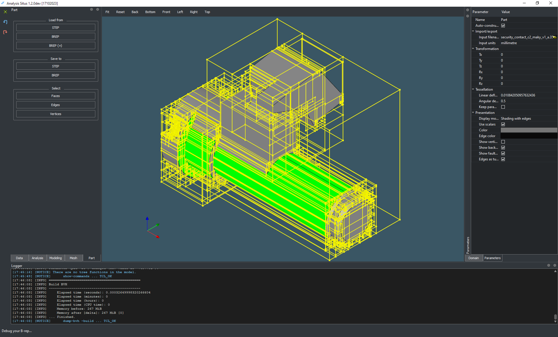 |
BVH constructed on the visualization facets. |
What we're looking for is an intersection algorithm that is insensitive to facets' orientation. If the intersection logic works for flipped triangles, it makes no difference how "dirty" our convex hull is. The only criterion for the tested mesh is that it adequately encloses the input part, with no gaps in the surrounding triangle soup. Aside from that, any dangling or non-manifold links, overlaps, degenerated or flipped triangles, and so on are no longer as problematic as with halfspaces, and the whole thing becomes considerably more robust.
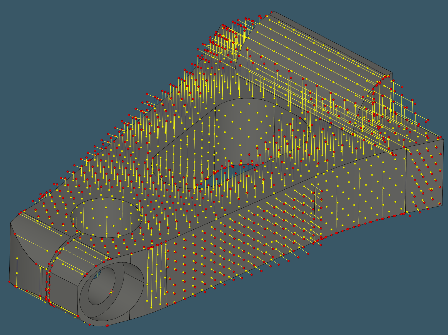
For each ray emitted from a probe point on a face towards the convex hull, we now perform a usual two-stage procedure. First, taking advantage of BVH, we filter out all bounding boxes that do not collide with the ray. This is known as "broad phase" collision test [Williams, A., Barrus, S., Keith, R., & Shirley, M. P. (2003). An efficient and robust ray-box intersection algorithm. Journal of Graphics Tools, 10, 54]. Once we have the tentative collision boxes, we dive into the "narrow phase" computation, which is designed to loop over the enclosed triangles and give them a shot against the approaching ray. Our implementation of the "narrow phase" is based on the paper by [T. Moller et al, Fast Minimum Storage Ray / Triangle Intersection].
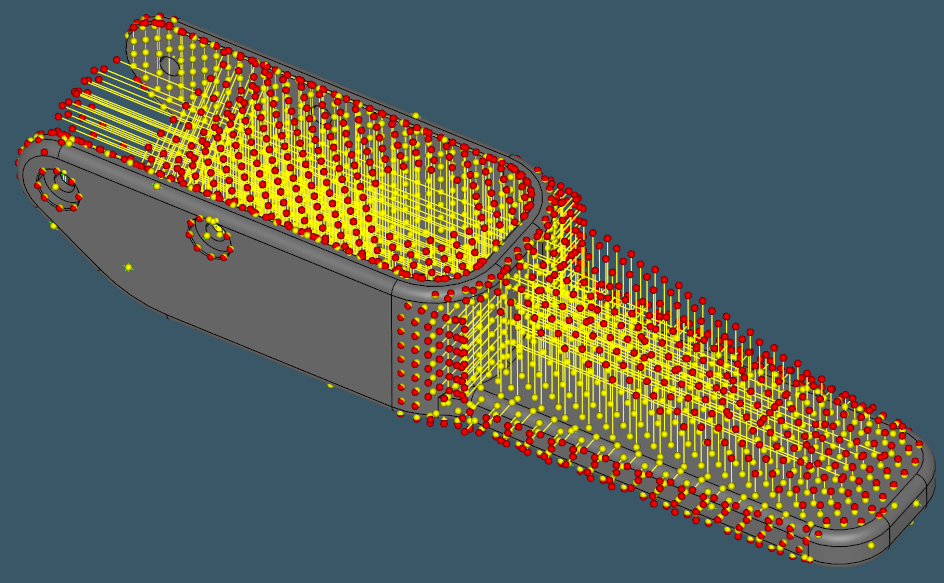
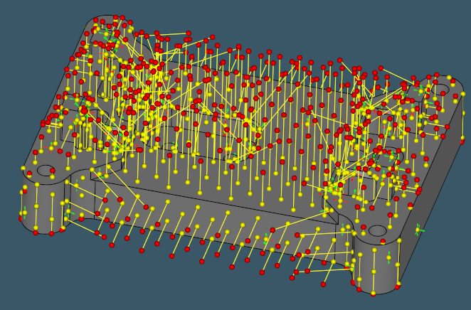
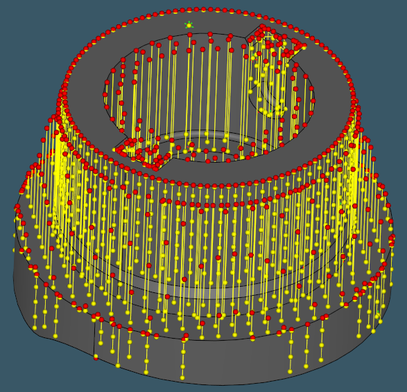
The images below illustrate distance-to-chull computation for a range of CNC-machined parts.
 |
 |
 |
 |
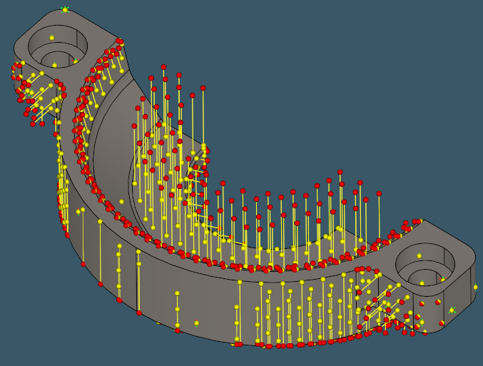 |
Depth probes over different milled parts. |
Want to discuss this? Jump in to our forum.