Profile recognition
Preamble
Profile bars, like bent parts or tubes, require laser cutting and so have a lot in common in terms of a computational approach for shape recognition. In this post, we will discuss several useful geometric heuristics for determining if a part has a profile shape or not. Various MaaS platforms dealing with sheet metal parts seem to provide similar functions for sheet metal analysis and quotation:
- Detect if a part is a folded sheet metal, flat shape, or profile (including different kinds of tubes).
- Recognize machining features and cutting lengths.
- Perform manufacturability analysis.
For the folded sheet metal parts, a dual flat pattern representation is usually constructed by unfolding. Such an unfolding algorithm should be quite advanced to work reliably and accurately in the presence of machining features and possible shape anomalies. For parts that do not involve bending (such as tubes and profiles), the unfolding algorithm has no use, but the employed recognition approach might get even more complicated. Indeed, profile-like shapes are not necessarily two-sided, and therefore, the recognition rules we adopted for sheet metal parts would not work here. Let's see what can be done instead to detect if a part is a profile or not.
Profile types
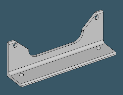
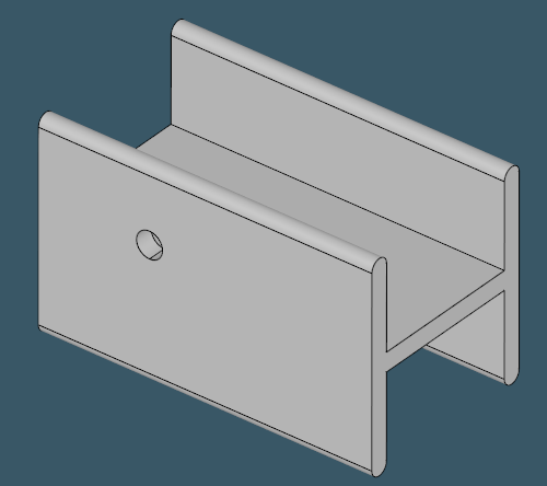
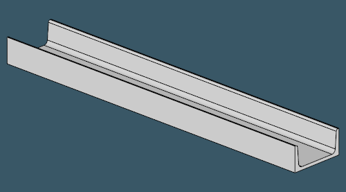
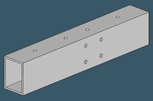
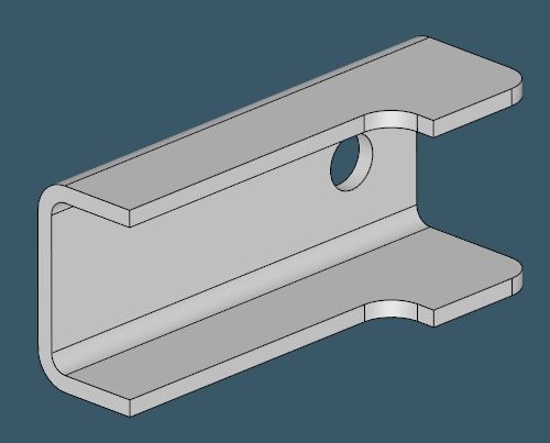
To start off, let's look at some typical profile shapes. From the pictures below, it should become obvious why people call them U-profiles, H-profiles, L-profiles and even I-profiles (assuming there's some difference between H and I).
 | |
 | |
 | |
 | |
 | |
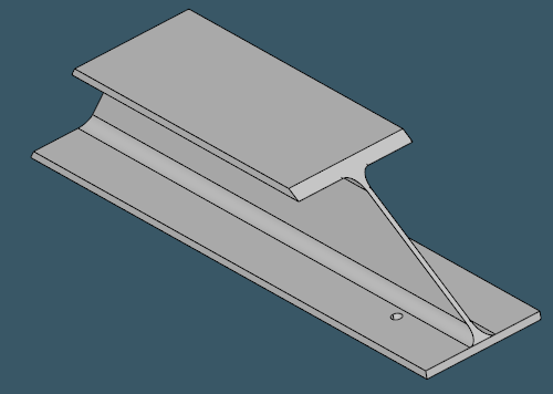
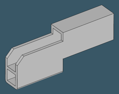
Another aspect of reliable shape recognition is how it behaves on non-profile parts. Here are some examples that might look like profiles, but they are (probably) not:
 |
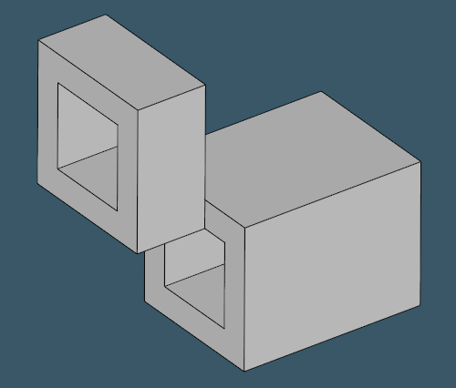 |
To make things worse, there are profiles that allow for being recognized as folded sheet metals. In such cases, the recognition algorithm does not have enough authority to decide on the intended type. The final shape classification might depend on the material thickness or manufacturing capacities of a specific shopfloor.
 |
For a solution to be complete, the 3D profile recognition logic should not only check if a part is a profile but also classify its type (U, L, H, T, etc.).
Why so special?
The driving idea of sheet metal recognition was the separation of a part onto two sides. We used a couple of preliminary assumptions to make such separation possible:
- A blank sheet has exactly two sides, and this "topological situation" would not change regardless of how crazily a part is folded. Therefore, every planar side face can be matched with an opposite one.
- There is always such a thing as a bend feature, which is simply a pair of cylinders in 99.9% of cases.
 |
Based on the observations above, it is not difficult to come up with the fundamental recognition logic for a sheet metal part: we take one stationary face, find its opposing face, and perform region growing across all cylindrical bends until all flanges are visited. The problem with profiles is that both of these assumptions do not work for them.
Towards prismaticity check
If you think a little about what makes profiles different from other shapes, you would most likely conclude they are all prismatic. It implies that you can geometrically extend a reference slice of a profile along the profile axis while making sure that the extruded prism sweeps all boundaries and leaves nothing outside. How can we check if a part is prismatic or not?
A prism is a shape generated by extruding a planar sketch in its perpendicular direction. Therefore, to classify a shape as a profile, we need to extract these two ingredients: a planar profile and the extrusion direction. The latter is also called a profile axis. If we know the axis, the subsequent recognition steps become more or less easy to conduct:
- Let's slice the model with a stack of planes perpendicular to the profile axis.
- Let's check if all slices are sort of uniform, i.e., there are no outliers if we project all slices onto the bigger (reference) one.
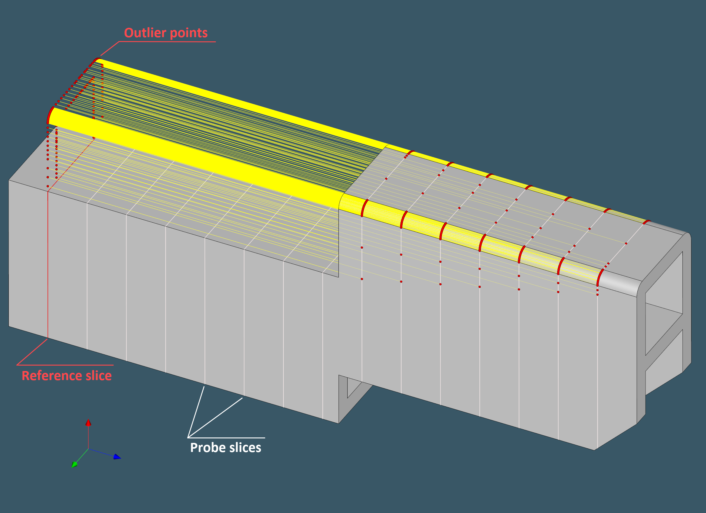 |
The image above illustrates a shape that is not a profile with respect to the chosen reference slice. The emphasis on the reference slice selection is not accidental. Proper selection of the reference slice is a key to successful profile shape recognition. This becomes especially clear if we recall that a "profile" is nothing but a two-dimensional contour. Below is a set of representative pixmaps that can be used to derive a profile type by image matching. Such images can be obtained automatically by sampling the detected reference slice with a prescribed grain size.
 |
These pixmaps, of course, tell nothing about the additional cutting required along the profile bar to produce the final product. As a result, while profile type detection can be handled in 2D, the overall recognition trouble remains three-dimensional.
Discussion
It can be difficult to obtain a reference slice from a profile shape sometimes. It is possible that the 3D model's cutting features are so widespread that the remaining bar can no longer be regarded as a profile. In such situations, whatever slice we choose in the model, another slice may be classified as an outlier with respect to the chosen one. This is, of course, a limitation of the algorithm, but as experience shows, it is not seen too frequently.
Another important question is how to determine the profile type. One approach is to use "conservative" geometric heuristics with the goal of identifying the profile type from, say, the mutual arrangement of face normals scattered over the recognized side faces. Alternatively, given that we can extract black-and-white bitmaps of profile parts, it might not be such a bad idea to use picture matching, which should be fairly straightforward to implement.
Want to discuss this? Jump in to our forum.