Open challenges in automatic feature recognition
«Науку двигают наукоёмкие задачи промышленности». Жорес Алфёров
Preamble
In this post, we will look at some advanced feature recognition problems. This digest is far from complete, and I'm sure that some of you could add a few more challenges to the list. Still, this text is here to provide insight into problems we have been working on for several years, so take it as a little retrospective. None of the challenges listed below are just "theoretical": huge amounts of energy and time have been invested in resolving these or similar issues in the past by our team. Although this kind of information is pretty hard to comprehend without specific experience, I feel a need to spread the word and maybe increase interest in this exciting topic among our readers.
Problem 1: how to recognize lathed+milled parts?
As we saw earlier, an MTS (Max Turned State) is a stock shape resulting from the lathing process. Now, let's suppose that we want to add some milling features to the lathed MTS piece and, in this way, finalize the part. This is where some interesting questions about automatic feature recognition arise.
Question number one is whether we can automatically determine the production type (turning and/or milling) from the input CAD part. How can we know if a part needs to be lathed in the first place? It appears that its rotational symmetries play a role, but a complete solution is not as simple as it may appear.
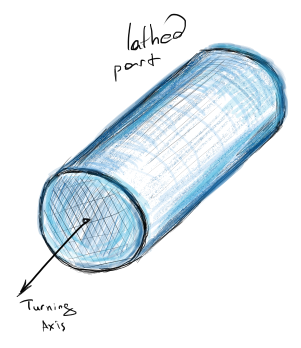 |
Lathed part. |
Question number two is whether we can identify and measure how exactly material is to be removed? Answering this question would allow for proper selection of tools.
Knowing how much milling is required is important for preliminary cost estimation. Here, we might also want to distinguish between roughing and surface finishing. Roughing is related to how much of the volume we subtract from the stock shape. Surface finishing is a more delicate process that is concerned with the total surface area traced by a tool. For example, SEER-3D software by Galorath recognizes different types of surface finish operations. And their reference guide is a nice introduction to the topic of CNC cost estimation as such.
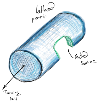 |
Lathed part with a milled feature. |
Problem 2: how about neural networks?
A commonly acknowledged problem in feature recognition is the difficulty of processing interacting features with deterministic methods. There is actually another trendy research branch that is related to artificial intelligence in feature recognition, but I never saw it in action and frankly doubt it's even worth mentioning. Having said that, it would be completely unfair to leave aside the remarkable research on AI-driven feature recognition conducted by Autodesk: their BRepNet "topological message passing system." So far, it looks quite promising as it delves into the complexity of topological data structures and does not try to oversimplify shape description with point clouds or meshes.
The open question, though, is how smoothly would it work compared to traditional rule-based recognition? I was surprised to read in "On-demand manufacturing platforms are taking the sector by storm" a statement that "on-demand manufacturing platforms leverage artificial intelligence (AI) to recognize geometric features of the requested part." Although published in a respectable-looking flyer composed by seemingly serious people, this statement is nothing but a false generalization. To the best of my knowledge, all successful feature recognition approaches working on CAD geometry in MaaS are based on deterministic rules. Still, machine learning can be applied when it comes to quotations. In the latter case, AI is employed to guess similar prices for similar parts while still knowing nothing about features or design intent. That's the whole thing about approximation: recovering missing data from already-known data chunks.
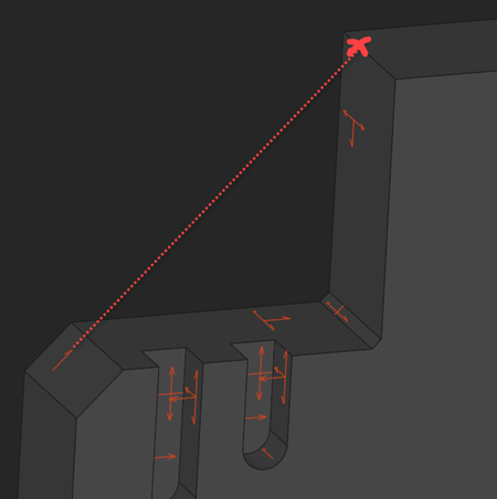
Problem 3: how to detect allowed milling axes?
Searching for a deterministic feature recognition method should normally be guided by pragmatic sense. What are we actually looking for? Do we really need to comprehend that a given group of faces is a specific variation of a pocket or a slot, possibly interacting with other pockets and slots? Or would it be enough to know that some faces are side-milled while some others are end-milled?
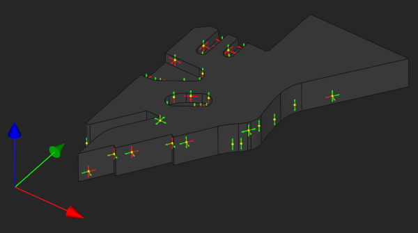 |
A sample part with its side-milling, end-milling, and impossible (red) milling axes recognized automatically. |
As it appears, recognition of milling axes for the face in question is a good step toward extracting somewhat more complete information about the whole machining process. If we know that a group of neighboring faces is side-milled, then we can assume that there's a cutting trajectory (a closed or an open contour) to finish these faces all along.
It is interesting that recognition of milling axes should employ a bit of a manufacturability rationale. For example, the presence of a concave sharp edge in the model would narrow down the milling possibilities around this feature. In some situations, we can cancel many candidate axes by doing a local topology analysis. One of the useful heuristics here is the analysis of vertex convexity, which was recently introduced in Analysis Situs. To check if a vertex is concave, convex, or smooth in a planar domain, we check its neighborhood: the idea inspired by a good old paper from Rochester [Requicha & Voelcker. (1984). Boolean Operations in Solid Modeling: Boundary Evaluation and Merging Algorithms].
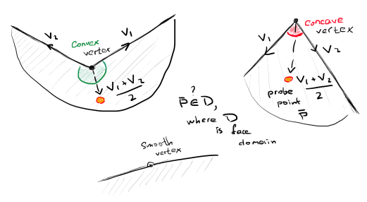 |
Convexity of a vertex is decided based on its neighborhood analysis. |
The local analysis is not sufficient, though. We must ensure that all the detected milling axes are not locked globally by any distant features of the part. This is where accessibility tests based on ray casting come into play. Such ray casting is a big topic in itself, so let's leave it for now and revisit it in the future series related to DFM.
 |
A side-milling axis is prohibited because it does not pass accessibility test. |
Problem 4: how to handle interacting features?
Once the milling axes are known, the corresponding AAG attributes are attached to the B-rep faces, and this way we grow the volume of knowledge about a CAD part under revision. The information about milling axes can now be used for deriving a somewhat upper-level knowledge about the part. In particular, the following features can be extracted based on the milling axes:
- End-milled faces (bottom faces).
- Side-milled walls contouring the given bottom face.
- Slots and grooves.
- Steps.
- Engravings.
- ... and others.
Different applications would come with different demands on the extracted properties. Below is an example of an open "step" feature that allows for being machined in two perpendicular directions. The same axes can be used to group individual faces into a somewhat meaningful feature.
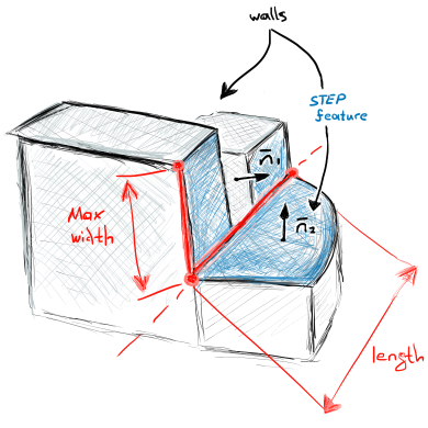 |
Step feature with some extracted props. |
Problem 5: how to identify setups?
Knowing the approach axes for the detected features opens the door to finding setups. A "setup" is a manual (hence time-consuming) procedure of reclamping a part in a machine, e.g., flipping it to access the otherwise hidden features. A good machining simulation will not only derive the number of required setups, but would also check their reliability by assessing the clamping contact zones.
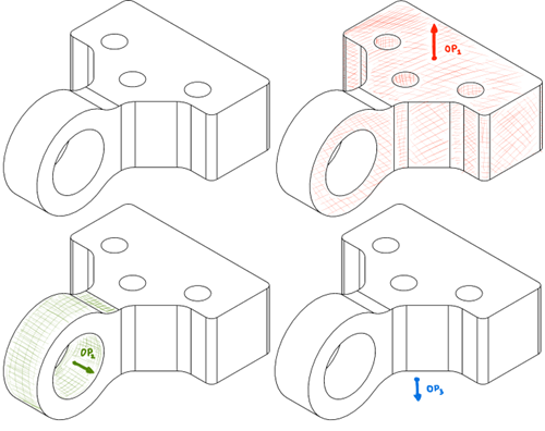 |
Possible milling ops (setups) for a part. |
Finding setups is a challenging optimization problem which employs several criteria. One way to formulate it is as follows. Given a universum of feature variants F, find the shortest possible sequence of operations O to fabricate all the features without repetitions. Let S be the setup finder function that maps the feature universum F to the list of milling operations O:
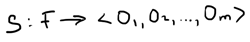 |
Setup finder function S. |
The order of operations is critical as the order defines the number of ops: depending on the order of operations, a part might require different number of setups as the same feature face generally allows for being fabricated from different directions. Now, if we agree that the goal is to minimize the number of ops, we have to parameterize the function S in a way that any argument's change affects the number of list elements. Such parameterization is not given for granted though. If an argument's variation does not affect the order of ops, then we just waste iterations and reevaluate S as the same sequence of ops over and over again.
The number of possible setup sequences is m! (factorial) where m is the initial number of distinct milling axes. Although direct permutations of those axes might end up in a sensible order, they would not account for the geometric significance of features and will force the setup finder to test pretty hopeless configurations. Therefore, in order to solve the optimization problem, we have to vary the order of ops more or less forcibly while keeping an eye on the tested order, so that the most significant ops take precedence over the less significant ones.
Problem 6: how to assess rough-milling volumes?
Volume decomposition aims at detailing how raw material is subtracted from a stock shape to produce a part. Decomposition algorithms search for features in the "delta volume" which is the Boolean difference between a stock and a part. Direct decomposition techniques are cumbersome as they require a number of Boolean operations to be performed one after another. Although there are many papers presenting such decomposition techniques with OpenCascade as a kernel, it will be safe to claim that OpenCascade's Booleans can hardly manage realistic parts and only work for simple prismatic cases. Intensive running of Booleans for decomposing parts of even moderate complexity is far from being an efficient (even viable) solution.
 |
Feature-based delta volume decomposition of a prismatic part. |
Still, volume decomposition with OpenCascade remains possible. Amazingly enough, the key to efficient and accurate volume decomposition is the same feature recognition we've been talking about the whole article.
 |
Another example of feature-based delta volume decomposition of a prismatic part. |
The trick is to use the recognized finished surfaces and milling axes to approximate the corresponding negative volumes. Another simplification that should be fair for MaaS (Manufacturing as a Service) platforms is to avoid computing explicit volumes for secondary features, such as fillets and chamfers. The topology of fillet/chamfer chains is often so tricky that any attempt to evaluate the explicit boundaries of the corresponding negative volumes might be prohibitively time-consuming and error-prone.
 |
We can use the prismaticity property of a feature to approximate its negative volume. |
Another direction of research towards the approximation of negative volumes is avoiding Boolean operations on B-rep and switching to a somewhat ad-hoc data structure where Booleans are not that difficult. This can be a voxelization or, potentially better, dexels or even meshes. Boolean operations on meshes are, of course, not that easy to implement, but they promise much higher performance and reliability compared to precise boundary evaluation.
To conclude, if I were to formulate an open challenge in negative volume classification, I would propose to search for a combination of B-rep feature recognition plus mesh-based Boolean operations. In this paradigm, we can use the luxury of analytic geometry to extract feature props. Then, to assess negative volumes for rough milling, we employ meshes, and this way we escape the well-known robustness and efficiency problems of B-rep Booleans (although sacrificing accuracy).
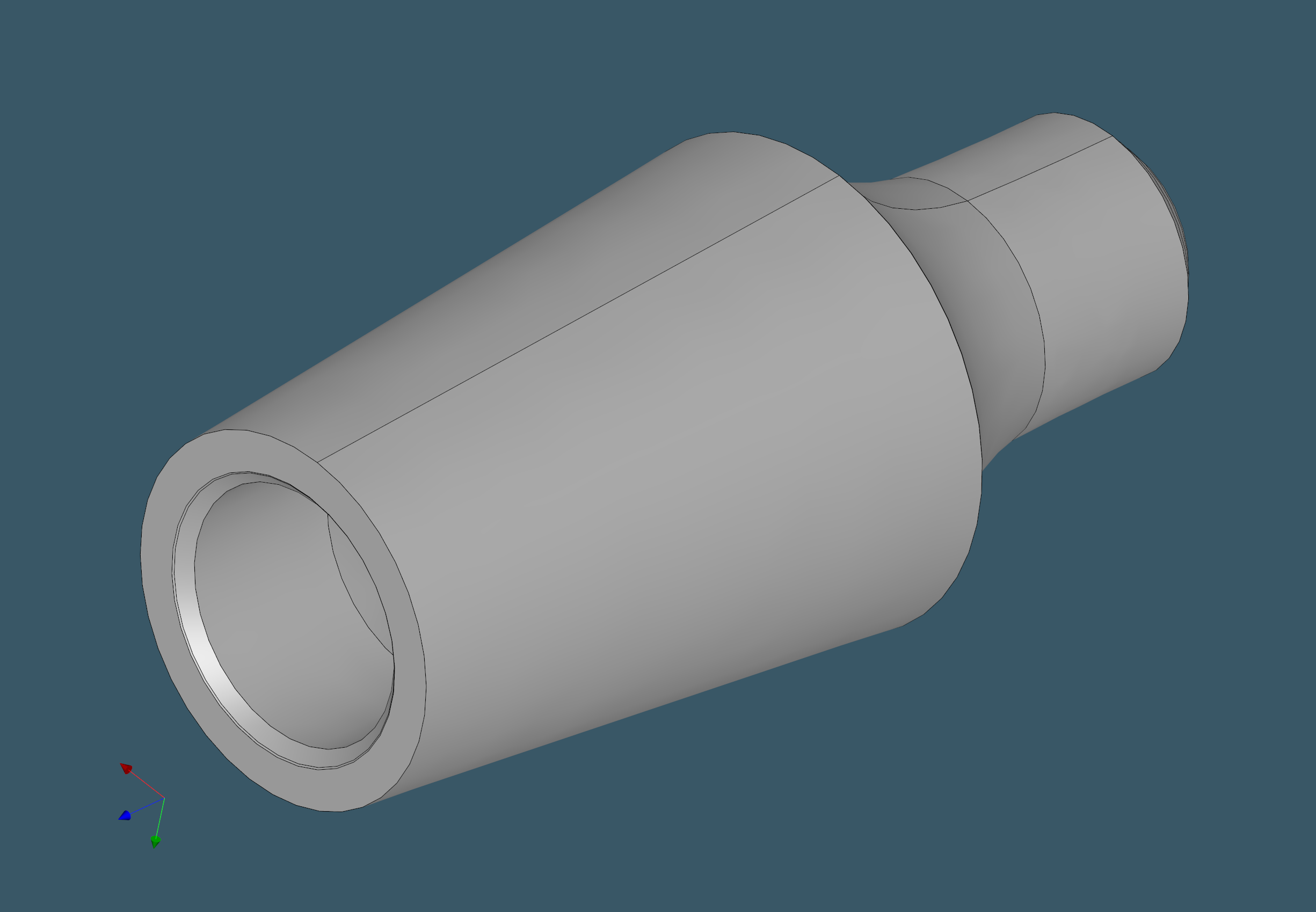
Problem 7: how to assess turned volumes?
Turned volumes, like milled volumes, must be broken down into specific machining features, such as bores, steps, and grooves. However, unlike milling, the volume breakdown of a turned object may be done in 2D due to its intrinsic rotational symmetry.
 |
Lathed part with multiple milling features. |
 |
Max turned state (MTS) of the part above (constructed automatically as a precise B-rep model). |
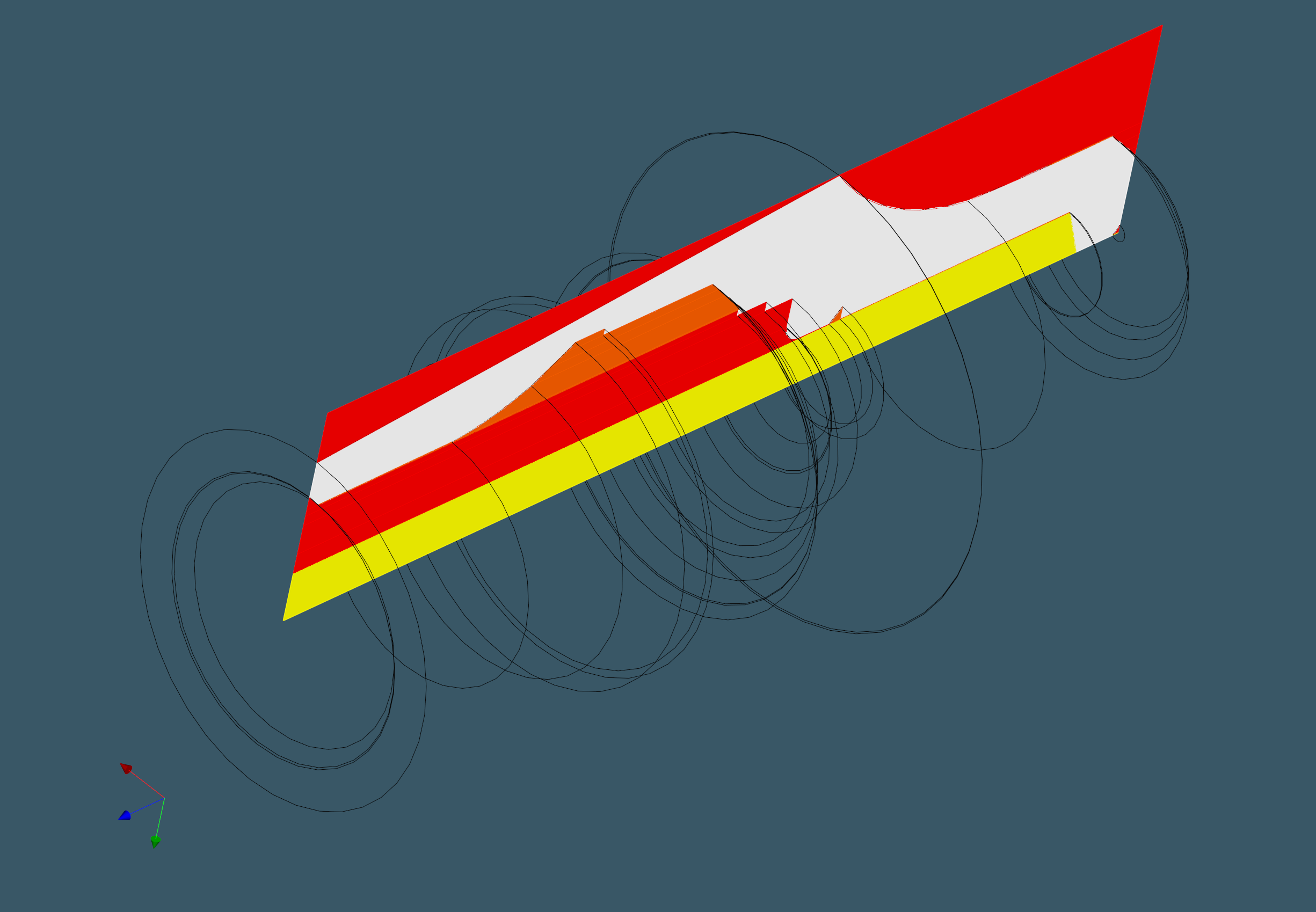 |
Swept profile face (white) and negative volumes: steps (red), grooves (orange), central bore (yellow). |
Knowing a part's bounding bar and the part itself allows us to break down the negative volume into a set of features using appropriate tessellation of the 2D domain. Instead of computationally expensive Booleans, we can use something more appealing: 2D ray casting. Depending on the arrangement of turning features, each vertex of a turned profile shoots a ray in either the horizontal or vertical direction, hitting a part or a stock. The obtained cells can reveal a great deal about tooling, part complexity, and machining time.
Problem 8: how to conduct manufacturability checks?
CNC feature recognition goes hand in hand with manufacturability analysis. There are two important points about the AFR-DFM relationship:
- To accurately identify features, we have to employ manufacturability analysis elements. This is what we do, for example, to choose milling axis candidates for each CAD face.
- Without DFM, feature recognition is incomplete. However, accurate DFM tests require significantly more computing power than recognition. As a result, comprehensive DFM checks are better arranged as post-processing logic for AFR.
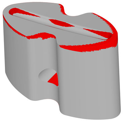 |
Thickness check in manufacturability analysis reveals potentially too-thin zones. |
Among the DFM inspections, we should test feature accessibility, wall thickness, feature clearance, hole depths, and so on. We will definitely return to this intriguing DFM topic in the future series to walk through some of the computational complexities involved. Meanwhile, you might want to read our NUMGRID 2022 conference paper, which delves deeper into the DFM mechanics.
Conclusions
Fast, reliable, and accurate feature recognition is only part of the equation. Many more components are required to create a piece of CAM software. For an automatic quotation system, the missing puzzle pieces would include machining time estimation logic and pricing criteria. None of these aspects were addressed above. Material removal simulation is an essential tool for realistic CAPP, and it certainly deserves a whole book to explore all of the challenges surrounding it in depth. We barely touched on tooling and said very little about DFM, despite the fact that manufacturability analysis is of great importance.
After many years of research and development in AFR, CAM, and other relevant subjects, I have to admit that I hardly know enough to lecture you here. Our part of the deal is to create geometric support for engineering technology, while engineering is, of course, way more engaged than playing with geometry. Still, making machining CAD more affordable and seeing it work in the industry feels good enough to justify the existence of this blog and Analysis Situs as software.
Want to discuss this? Jump in to our forum.