On sheet metal recognition and unfolding (Part 1)
"For me, good design means that when I make a change, it’s as if the entire program was crafted in anticipation of it." Game Programming Patterns — Robert Nystrom.
We have touched the topic of sheet metal recognition and unfolding indirectly in this blog before. Here are some links to check out:
Sheet metal is one of the most convenient object types for a computational geometer. In most cases, it is possible to recover all features from a "dumb" STEP file (or any other feature-free format) and unlock further processing of a model in a direct manner. The simplicity of a sheet metal part is due to the types and specific order of its faces. Specifically, planar sheets follow cylindrical bends and vice versa. By visiting sheet metal faces recursively, one can distinguish both sides and deduce the object type (e.g., flat plate, folded sheet metal, or tube).
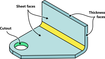 |
A simple sheet metal bracket and its inherent face types. |
There are quite some tools that allow us to design and manipulate sheet metals. As a big fan of the direct editing paradigm (that's likely because I am not an engineer and simply appreciate responsive UI), I'd pay particular attention to the software packages capable of recognizing "dumb" models for subsequent unfolding:
- SpaceClaim
- BricsCAD
- Amazingly enough, FreeCAD
- Our Analysis Situs SDK can do that job as well
I am sure there're many more tools to do the recognition and unfolding job, but I never tried or heard about such their capacities (shame on me). The only free package available among all existing options is, of course, FreeCAD with its unfolding algorithm by Ulrich Brammer.
Unlike SpaceClaim, FreeCAD (ver. 0.18) seems to leave possible self-overlappings of a flat pattern undetected. However, that's not a big deal, as such verification (based on OpenCascade's Booleans) can easily be added (if someone wishes to contribute that to FreeCAD). We will touch on some of the nuances of sheet metal processing in the future series of MG.
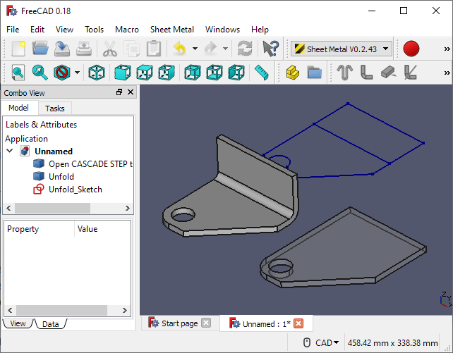 |
Sheet metal unfolding in FreeCAD. It's not bad at all. |
Unfolding in SpaceClaim becomes available once a part is recognized as sheet metal. SpaceClaim allows for identifying certain feature types, such as louvers, bridges, hems, etc. Hence it's quite powerful, although I always struggle a bit with the UI workflow (i.e., which buttons to click in what order).
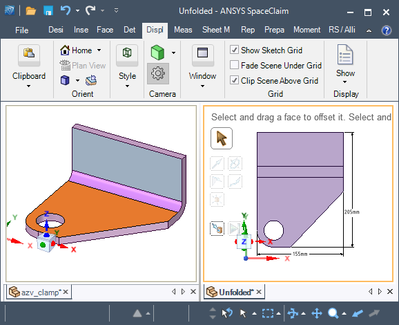 |
Sheet metal unfolding in SpaceClaim. |
Our in-house SDK recognizes different sheet metal features without asking the user to enumerate their types beforehand explicitly. Unlike FreeCAD and seemingly SpaceClaim, it also counts the detected features and derives some handy props such as the stock area, its perimeter, etc.
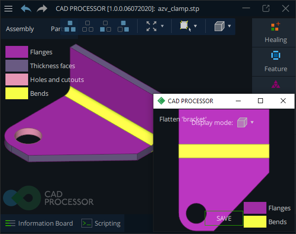 |
Sheet metal unfolding with our SDK. |
Now let's talk about the unfolding algorithm in general. Although that's seemingly a simple thing, there are many subtle issues to address to implement the algorithm properly.
First off, like in any other geometric algorithm, there should be a driving idea. Without such, any algorithm facing high enough "selection pressure" is doomed at becoming a big ball of mud impossible to maintain. The key idea behind sheet metal unfolding is splitting up the CAD model in two sides. Once you're armed with AAG, graph theory's formalism starts serving you and shortly pays off.
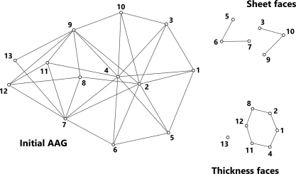 |
Connected components of AAG used in the course of recognition. |
The graph should be splittable into a couple of components representing the upper and the lower sides of sheet metal. The graph nodes to exclude for such splitting form up a chain of "thickness faces." That idea is clear and simple yet powerful to sustain a lot of realistic cases.
Unfolding is a two-ingredient thing:
- Rotating the flange (sheet) faces to lay them down onto the reference plane.
- Unrolling the cylindrical bends taking into account deformations.
As usual, there are many subtle issues to address in development, e.g., how to reliably measure the thickness or process features, such as louvers or ribs. We leave all these nuances for now. What's really important is the code architecture, i.e., how you put these logic bricks together. It is hard to say if code architecture is an art or craft, but you'd probably have to write the same thing repeatedly before you start to understand what good architecture is. In the upcoming blog posts, we will touch some puzzle pieces more in-depth, so stay tuned.
Link on Medium.com: On sheet metal unfolding (part 1)
Want to discuss this? Jump in to our forum.