On edge cases in CAD thickness analysis
Preamble
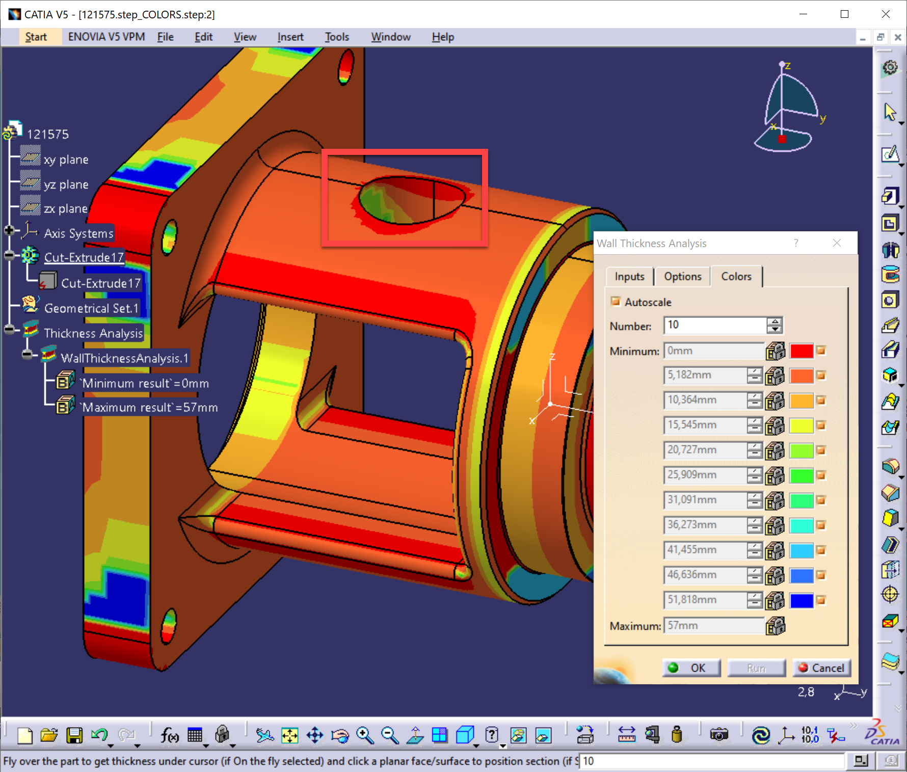
Knowing the thickness of walls and ribs is important for calculating the allowable stresses and strains of a machined part. It is also something you might want to assess when working with molded pieces because thickness is one of the manufacturability constraints (something embraced by DFM = Design for Manufacturability). If not convinced, you may want to read this paper by GeometricTech, which contains interesting hints on the entire approach.
In Analysis Situs, we have "ray-based" thickness analysis available under the permissive 3-BSD license. The principle behind this computation is quite trivial: triangulate the part, fire a ray from each triangle to the model's inside, and find intersection points. The algorithm is simple yet practical. This code is in use by some commercial organizations for quick assessment of possible thin regions in a part without any user interaction. But, as it always happens, evil is hiding in the details. Or in the features.
Take a look here:
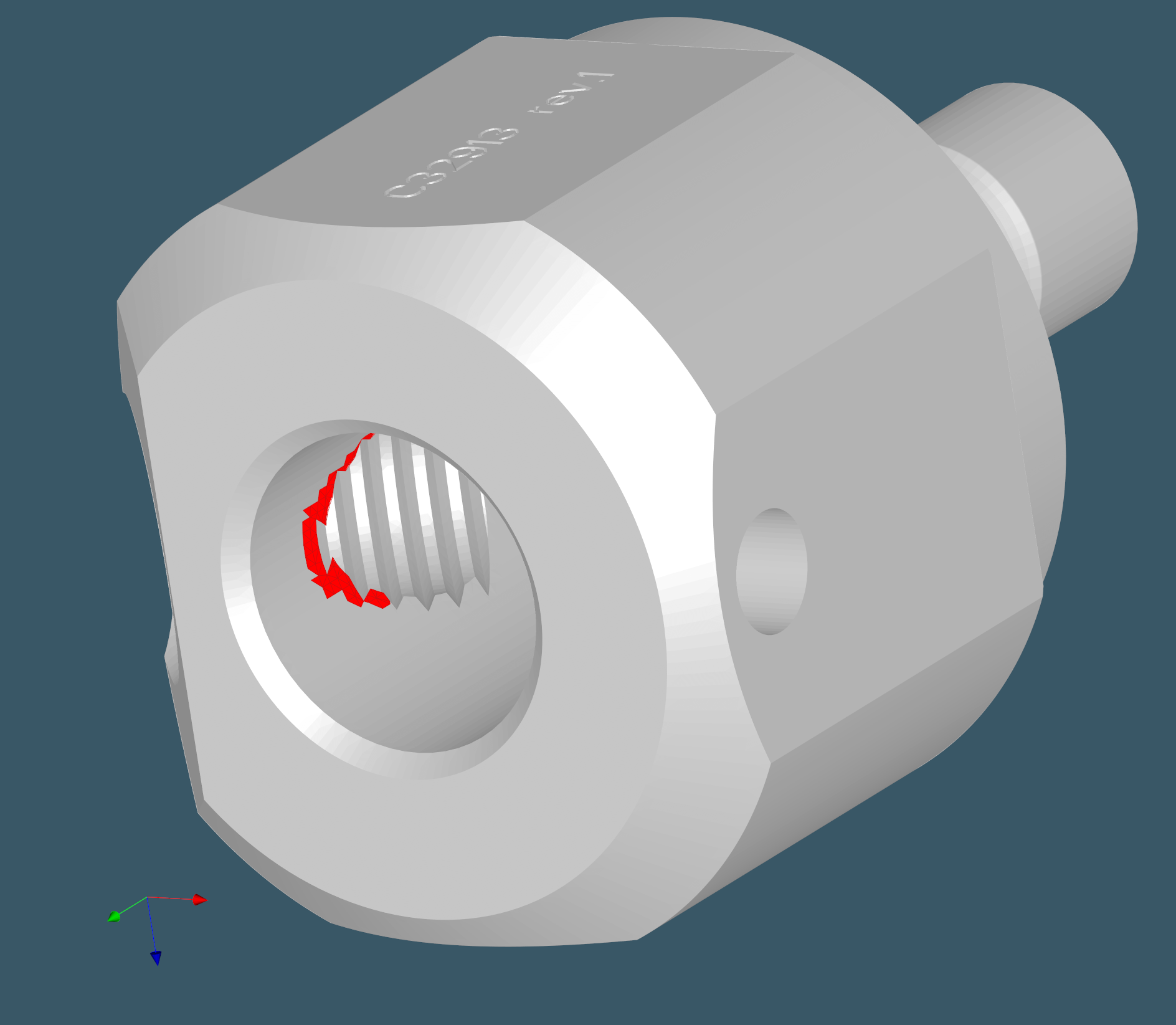
 |
Thickness detection artifacts. |
Here we have a plain cylindrical hole drilled in a cylindrical shaft. Such a geometric configuration leaves sharp edges at the insertion contour, and the thickness analysis yields false-positive spots. It's geometrically correct because the spotted triangles did not pass the minimum thickness check, and the material left in those zones is probably too thin. Still, if you hand this part to a machine shop, you'll unlikely get any trouble making it. This is where geometric reasoning does not entirely overlap with manufacturability concerns. And we have to do something about it.
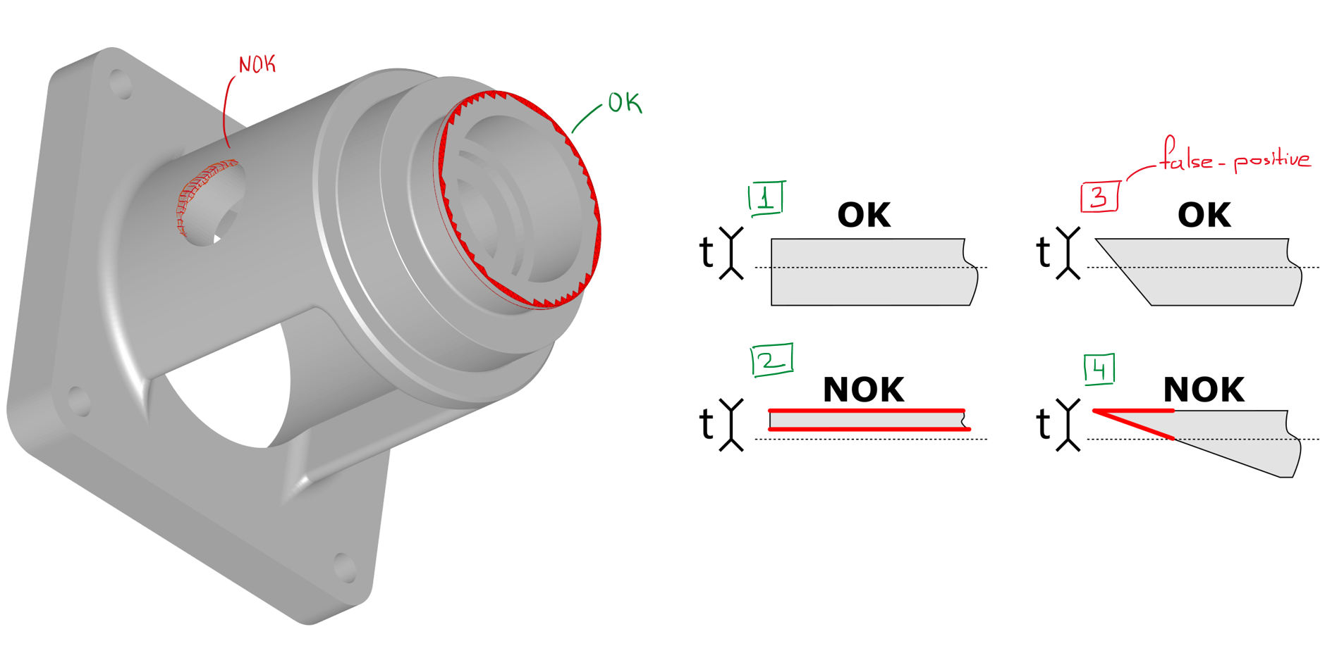 |
False-positive thickness spots might emerge at sharp edges. To compensate for this effect, additional heuristics are required. |
Although ray-based thickness computation is close to trivial, things are getting worse when it comes to polishing it. The thing is that all these ray casting techniques are blind with respect to common engineering sense. It's not surprising then to discover some elements of feature recognition even in such brute force algorithms as thickness or clearance tests. Let's now see what it takes to avoid false positives in the thickness analysis.
Good mesher
Here by "good" one, I mean none of these open-source solutions, although you might argue that these solutions are often just fine. Not for DFM though. In DFM, what matters most is the ability of a mesher to generate uniform surface mesh within reasonable time frames. Quadtree decomposition techniques and alike would work best. But that's a story for another day.
Feature edge analysis
In our attempt to formalize the issue, we ended up with the following definitions:
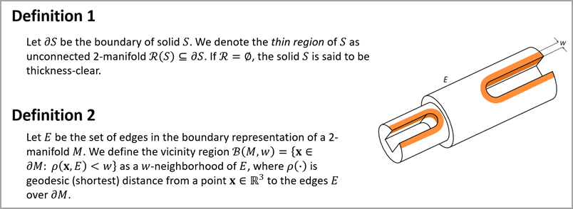 |
Definitions 1 and 2 serve to establish the vicinity B of the B-rep edges in the CAD part.
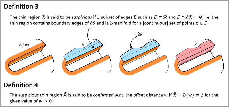 |
Sound formalisms are useful for precisely defining the problem and proposing solutions. The problem of filtering out false-positive thickness spots is two-fold:
- Find all suspicious thin regions (not necessarily connected).
- Confirm or cancel the found regions w.r.t. the given offset distance w.
Problem 1 is trivial to solve with ray casting. This is how far you can get without feature recognition. And that's a standard approach implemented in CAD software.
 |
Problem 2 must be handled if you wish to highlight only the problematic zones without leaving this duty to the user. It can be solved using simplification heuristics, as illustrated below.
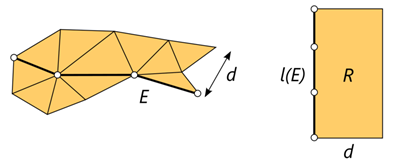 |
Knowing the area A of the thin spot R and the length l(E) of the edge set E, we approximate the unknown width d as A/l(E). Then, if d < w, the region R is subtracted from the reported thickness spot.
Features to skip
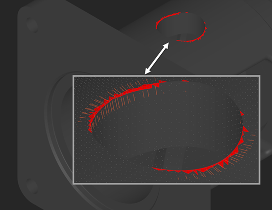
The thickness analyzer algorithm may safely skip several feature types that would usually result in false-positive thin regions. Examples include modeled threads and engravings. For modeled threads, thread pitches are a clear source of false positives. It is also typical to see thin regions on the walls with engraved text and logos.
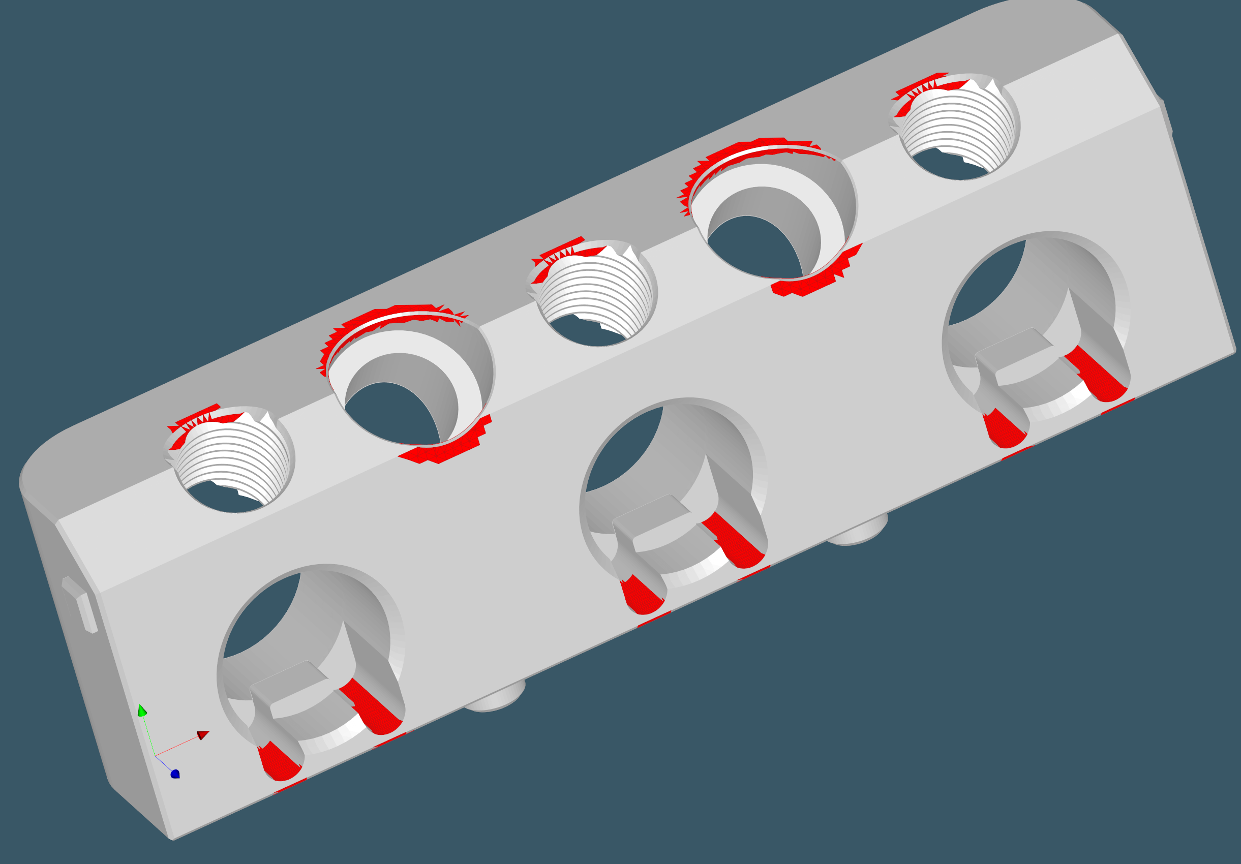 |
Multiple thin regions on a part with holes and modeled threads. |
To get rid of false positives induced by specific features, it is enough to exclude the corresponding CAD faces from the list of ray sources while leaving them as potential ray targets. Doing this filtering without knowing the part's features is impossible, and that is why such false positives are never filtered out in ordinary CAD systems.
Discussion
Thickness analysis has the flavor of one of the simplest algorithms in the entire DFM tool set. However, our experience with this algorithm appeared to be more involved than simply developing it and enjoying the results. There are a few key factors that cannot be neglected when building a decent thickness analysis tool:
- The right choice of a discrete carrier for the thickness field. That does not have to be a mesh; it can also be a point cloud, well, anything fast to compute, dense, and uniform.
- Ray-based thickness analysis goes hand in hand with sphere-based analysis, which is less trivial and deserves another post or two. Implementing one stimulates implementing another.
- Simply spreading a thickness field over a CAD boundary is insufficient for automatic DFM because it requires the user to interpret the results. When you go for automatic mode, all of these false positives are thrown at you, and the whole game stops being entertaining.
- Feature recognition is vital in making sure the thickness test produces accurate results.
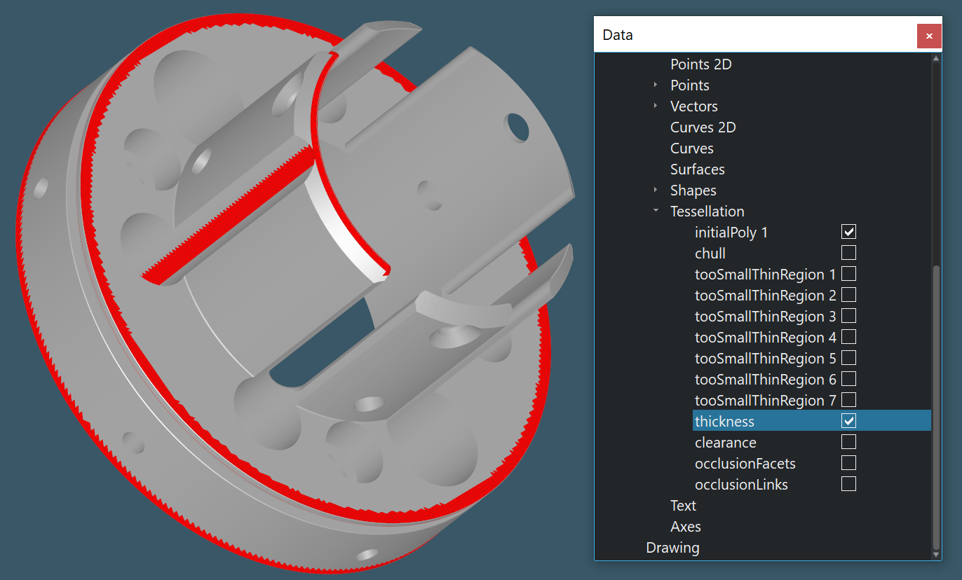
 |
Manual thickness inspection in Analysis Situs. |
The animation above shows how a computed thickness field can be evaluated by the user interactively. When the mouse cursor hovers over a triangle, the corresponding scalar is used to create a sphere with an equal diameter. Navigating over the mesh elements while looking at the spheres should give us a good indication of the measured thickness. Here are some examples of thickness issues that are not false positives:
 |
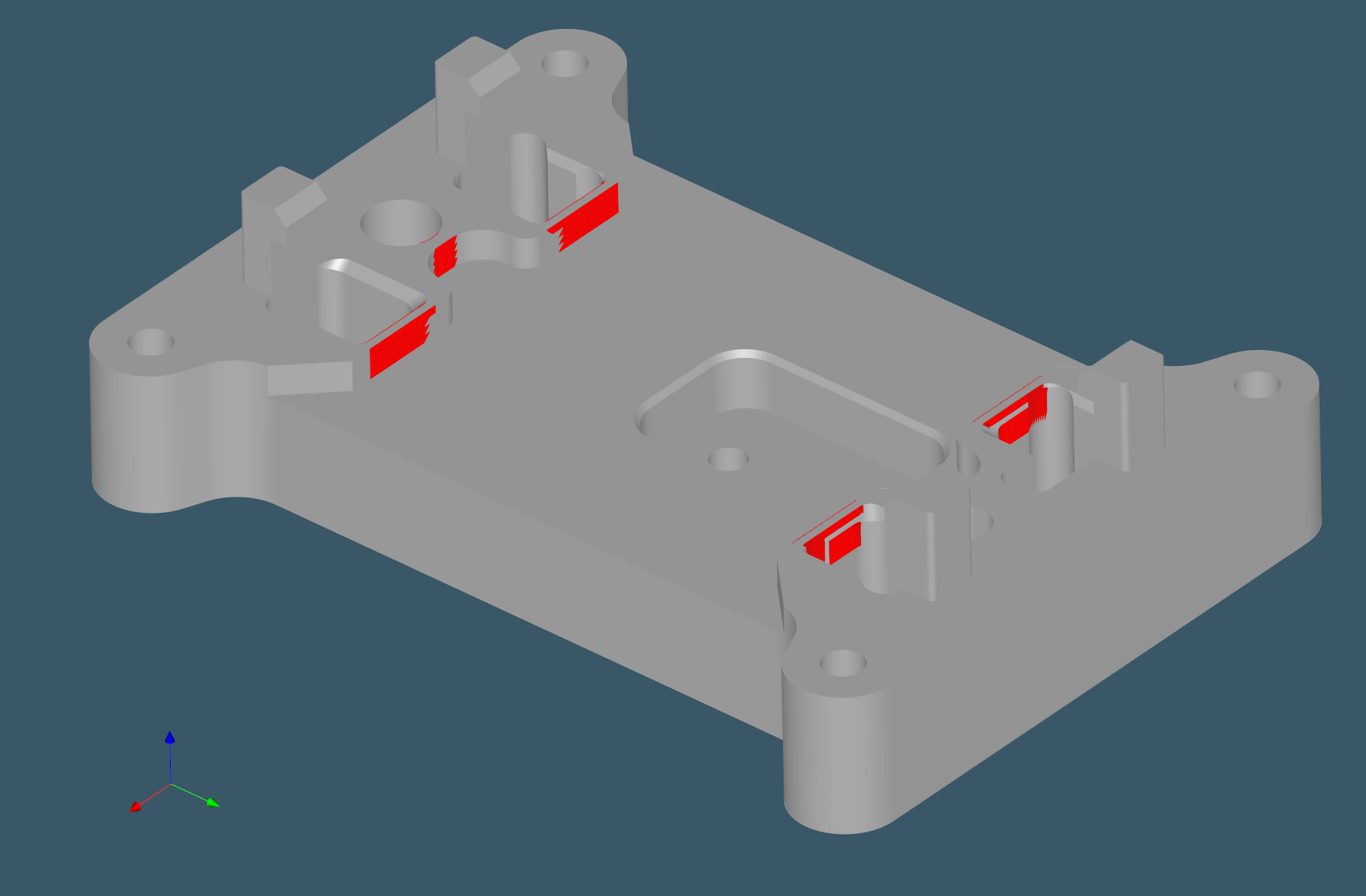 |
 |
Some examples of thin regions detected for CNC parts. |
Users typically wish to know the problematic thickness zones. Instead of staring at the colorful fancy scalar maps distributed over the CAD model's surface, it is better to direct the user's attention to certain locations while ensuring that the reported zones are not false positives. After removing false-positive zones, various analytics may be extracted to answer the following questions:
- What are the min and max thickness values in the model (except for the false-positive zones)?
- What is the total surface area of the too-thin regions in the model?
With such data in hand, we can create a somewhat automatic DFM system that frees the user from laborious tasks and allows them to focus on truly complex design issues.
Want to discuss this? Jump in to our forum.