On sheet metal unfolding (Part 4)
In our previous articles, we covered different aspects of a sheet metal unfolding algorithm. We started off by giving a brief overview of the principle and software packages implementing it. The second part was more mathematical. We explained how to unroll cylindrical bends without deformations using the approximation utilities of the OpenCascade open-source library. The third part was mainly devoted to applying a K-factor for obtaining realistic bend compensation elongations.
Surprisingly enough, the unfolding algorithm is a deep subject. To confess, I did not see much complexity back in 2017 when I started working on it. This thing seemed a piece of cake, and, in fact, its very principle really is. So let's talk about the core idea behind the unfolding computation. We might better have even started from this chapter because it outlines the essence of the algorithm.
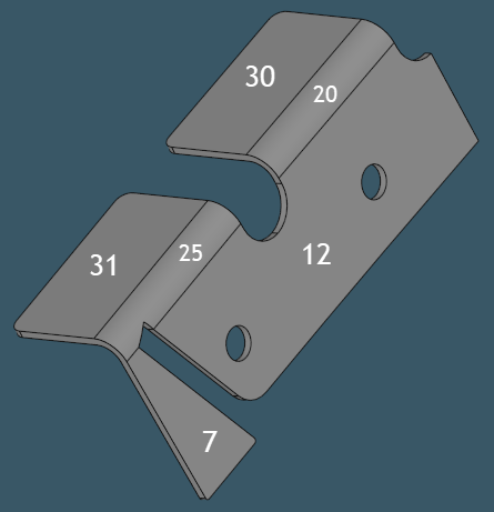 |
Sheet metal part with face indices to be used throughout computation. |
The algorithm's topological core is the unfolding tree data structure. Unfolding starts by selecting a reference face that defines the flat pattern's plane. From this face, we recursively visit all flanges accessible through the bend faces. Such propagation is done for one side of a sheet metal body, no matter which one. Along with the iteration process, we construct the unfolding tree data structure, whose nodes correspond to the flange faces and arcs represent the predecessor-successor relationship. The initial reference face becomes the root node. All flanges accessible from the root in a single unfolding operation are its direct children.
 |
The unfolding tree for the part presented above. |
The unfolding tree nodes come up with some attributes, helping to build up a flat pattern shape at the end. There is a handful of them. First is a list of references to the corresponding bend faces (a flange might be connected through several bend faces). Then, there is a flattening transformation matrix defined relatively to the parent flange. To get the ultimate location of a flange in the reference plane, it is necessary to stack up all the nodes' transformations in a path from this node to the root. A transformation matrix is computed as a product of elementary transforms:
T = TC R TR.
The following figure illustrates the notion of "border trihedron" that we use for the computation of elementary transforms. This trihedron is basically a local coordinate frame attached to an edge where a bend meets a flange. There is a specific convention we follow for labeling its axes. The VX axis is directed along the bend's edge. The VY axis points inside the face. The VZ axis is orthogonal to VX and VY.
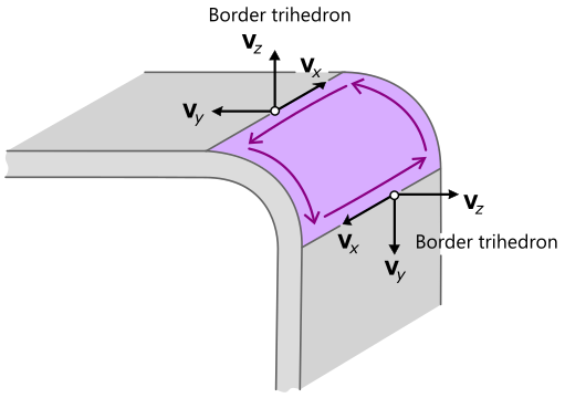 |
Border trihedrons that are used for computing the unfolding transformation. |
So the flattening transformation T is a product of three transformations TR, R, and TC, applied in the order we list them. Here TR is a translation to match the flanges' edges. R is the rotation by the value of bend angle, and TC is the bend compensation translation. The TC transformation depends on the K-factor passed to the unfolding algorithm or computed right away, based on the bend's radius.
 |
Border trihedrons on a sample model. |
Once the unfolding tree is there, we have everything to build up a flat pattern's geometric representation. Following the order in the unfolding tree and the encoded transformations, all flanges are paved to the reference plane. The paving procedure leaves gaps between the flanges to keep room for the unrolled bends. The geometry of a flange is nothing but a relocated copy of the initial face. The approximation of bends is a matter of choice. However, we prefer the polynomial approximation technique described earlier. The unrolled bends fill the gaps between the flattened flanges.
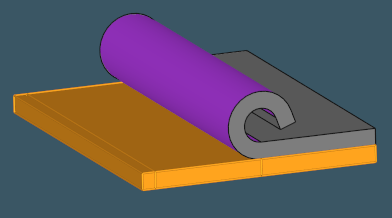 |
Unfolding of a simple bend of 250 degrees. |
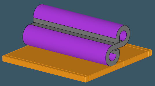 |
Here is one more synthetic example of an unfolded sheet metal shape (two bends of 270 degrees each). |
In the end, the resulting faces are optionally stitched together. A vital stage to be done here is verifying that a flat pattern is free of design issues, such as overlappings. Looking at the folded state of geometry, one could not easily find out that a part is not manufacturable (unless it's a trivial configuration of folds). We need a flat pattern for such diagnostics. A flat pattern is actually a dual representation of a CAD part. That very fact makes sheet metals so unique. Here's one relevant citation by Christian Lecomte, the grandfather of sheet metal workbenches in such products as SpaceClaim and BricsCAD:
"To simplify, the tool path for a classical mechanical part is mainly defined from its shape. In sheet metal, not at all. The machining is made on a flat sheet, and the part never looks like the design except after the last bend."
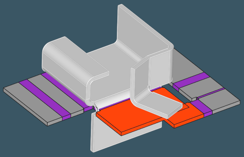 |
Here is a self-overlapping issue on a flat pattern after unfolding. The overlapping flanges are highlighted in red. |
Not all parts recognized as sheet metals can be unfolded. Some of them could not, e.g., the closed shapes, such as tubes, or infeasible geometries. Therefore, the unfolding procedure itself is a method of verification that your design is roughly correct. Some extra manufacturability analysis and technology-wise validations should come along, though. For example, measuring the clearances between bends and cutouts is another critical check. A cutout being too close to the bending line easily gets deformed after undergoing the press machine. Generally speaking, manufacturability and technology constraints might require sophisticated geometric processing as a backbone, but let's stop here today as that's another story.
Want to discuss this? Jump in to our forum.