How to survive B-Rep sharing and instancing
In the OpenCascade kernel, you have certain flexibility in the organization of a topology graph for your model. In particular, it is possible to reuse boundary elements, for example, by replicating the same face many times in a CAD part with different locations. While such a possibility may look flexible and is, indeed, useful in certain circumstances, it opens the door for tricky issues which are hard to debug. So let's speak a bit on this topic trying to answer the following question: is it a good practice to reuse the boundary elements by relocating them within the 3D model?
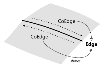 |
Illustration of sharing. Two faces sharing the same edge via coedge entities (pointers to the edge with a certain orientation flag). |
We start with a relevant blog post from the developers of ACIS. The ACIS guys state that "sharing is not a complex topic, it's a concept that was built into even the first B-Rep technologies." The post itself was devoted to a modeling failure which appeared to be the problem of a lossy data translator. To put the idea briefly, a CAD translation tool which does not respect sharing or whose support of sharing is limited is a "bad" tool. Thus you need to be careful when choosing your interoperability solution (needless to say which one is "good" after, right?). So let's put the main points on the table:
- A good modeler should support sharing. If not, that's graceless because even the modelers from dinosaurs era did support sharing of boundary elements (well, if the ACIS team meant "sharing" and not "instancing", that's a very reasonable statement).
- The B-Rep technology hides a lot of information from the naive user. Do not be surprised when your modeler fails: that's because your B-Rep is not healthy, and it is the 3-rd party to blame on corrupting your data.
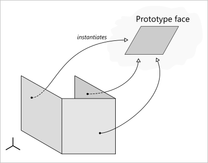 |
Illustration of instancing. In this example, a single (prototype) face is instantiated three times in a model. |
We are not going to argue with the position outlined above. Indeed, sharing and instancing are something very easy to implement at the level of a data structure. You simply make a pointer instead of copying the object and (optionally) associate a transformation matrix to give it a good placement. Easy? Well, yes. But only if you're looking from the perspective of a software architect. Now just imagine that you create a box whose six faces are all sharing the same planar face under the cover. What does it mean practically? It means that any change performed on any face of such a super-efficient box will have an implicit effect on the rest of faces (like drilling a single hole will give you six holes as a result). That's absolutely not something a human engineer would expect. So, to keep the data structure efficient while giving a human a clear and predictable behavior of a modeler, the kernel should hide a lot of complexity to treat the instancing properly. The modeling kernel should be ready to break sharing and construct the deep copies of the boundary elements whenever keeping the transformed replicas is not possible anymore (e.g., when the user starts drilling his holes). The same complexity applies to the shape interrogation API. For example, whenever asking for a host surface of a face, you should not forget to take into account its placement. Otherwise, you may get a surface in the wrong position. Finally, all geometric modeling algorithms should be aware of this instancing feature to treat it properly.
The complexity of a fundamental data structure has severe implications: the extra complexity of the modeling kernel itself and hards days for the maintainers. However, one can argue that such complexity is encapsulated in the modeling kernel, so why should I care? Here is a quote from a brilliant book [Corney, J.R. and Lim, T. 2001. 3D Modelling with ACIS].
... there is a difference, often forgotten in academic circles, between things that are hard and things that are impossible. It is undoubtedly hard, for reasons that will become apparent later, to write a robust B-rep modeler, but it is not impossible, as the existence of ACIS and other B-rep modelers proves. Many of the other modeling representations are simpler to implement so surely they must be better? No, not if someone else has already done the hard bit. I’m not bothered that it is hard to design and manufacture a working internal combustion engine, because I’m not going to do it. I am simply going to buy one and use it.
Here we need to make a couple of remarks. ACIS is sometimes called an "open" modeler but it is not really evident why. Previously, we could, at least, check the online documentation of ACIS to get a basic understanding of its capabilities. But that's not the case anymore. While ACIS is not that open (well, it is just a commercial package, why do they call it "open"?!), it is also not the only kernel on the market. There are at least Parasolid, OpenCascade, SMLib, and C3D (but not only them). All these kernels have to communicate with each other whenever you pass data from one CAD system like NX to another like Catia. The new level of complexity arises at this stage because the data translation code should understand all "geometric languages" and to accurately convert one B-Rep data structure to another. At this point, the complexity of a modeler is not anymore the internal matter of a modeler. Anyone, who will try to program such a data converter, will be bothered with the mentioned complexity and all its implications. If you want to communicate two geometric kernels, you will need to do something about instancing and sharing. In no way, you may simply ignore it.
 |
Checking internal locations of boundary elements in Analysis Situs. |
But Ok, this blog post is not to say "avoid instancing" or "avoid sharing" (that sounds really stupid) or something like that. It is more to share a bit of pain which I experience whenever the instancing of boundary elements enters my life. The first point where you need to start caring about locations is the shape equality check. In OpenCascade, there are three methods declared in the TopoDS_Shape class to compare B-Rep structures:
- IsEqual() returns true if the shapes point to the same geometric and topological data structures, have identical orientations and locations.
- IsSame() returns true if everything is identical except orientations.
- IsPartner() returns true if the geometric and topological structures are the same while locations and orientations may differ.
All these methods can be invoked directly or indirectly, e.g., if you are using hash tables (depending on the hasher, one or another method can be used to check the equality). It should be noted that locations will be checked by their transient memory addresses, not by the contents. This means that if somewhere in your code you happened to deep-copy the location from one instance of a shape to another (while keeping the same pointers to the B-Rep elements), IsSame() and IsEqual() checks will return "false" for the locations which are meant to be equal. The latter fact is kind of counter-intuitive as normally developers picture the shape locations as the scalar values comprising the transformation matrices. Beware of this small trap.
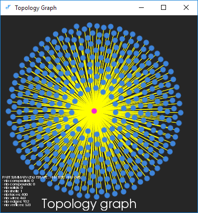
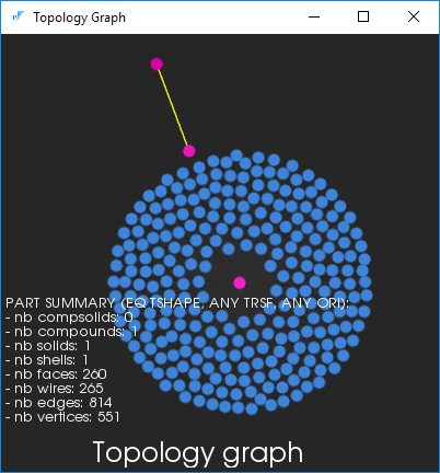
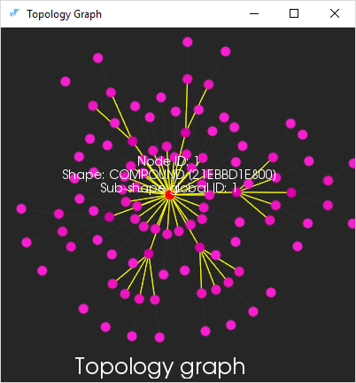
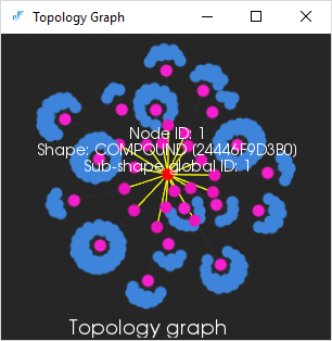
The following picture illustrates a topology graph for a CAD part whose boundary elements have some non-identity locations (instancing relation is shown with yellow links). While formally perfect, this model does not look healthy. Any modeling operator applied to this kind of a B-Rep structure will have to transform all geometries prior to working with them. Formally, it is even allowed to have some tricky transformation matrices defining non-uniform scaling, mirroring, etc. While giving no additional descriptive power in the sense of geometric modeling, such shape representations tend to put a higher pressure on the algorithms. Those shapes look really like someone is cheating the modeling API of a kernel and provokes it to fail.
 |
Locations at faces. |
The transformations which are meaningful in part design should probably be applied at the level of a part itself. Returning to our graph view, it is more logical to have transformation matrices at the top level of the topology hierarchy, so that you have a transformed solid or a series of nested transformed compounds. However, even in the latter case, there is something to think about. Having a series of nested compounds with transformations ask yourself: aren't you trying to represent assemblies by means of B-Rep entities? Is that what you really mean? If so, just think of some better structures, such as HAG or a database.
 |
Location at the top level of a topology graph. |
 |
Assembly-like internal locations (still Ok, but isn't it better to have a real assembly structure instead of B-Rep entities here?). |
To see if the instancing technique is common or not for the internal boundary elements (such as faces), we used the following command of Analysis Situs:
check-internal-locations -f
This command returns 1 if any internal locations are detected. The "-f" key specifies that we are looking for the locations associated with the faces only. The check was done in a batch mode for many STEP and BREP files which I found on my machine. Here is an example of a script for recursively visiting and checking BREP (*.brep) files:
#------------------------------------------------------------------------------
# This script checks for internal locations in all CAD parts located in
# the specified target directory.
#------------------------------------------------------------------------------

set workdir "C:/users/ssv/Desktop/test_cases"
set targetExt "brep"

set filenames []
set faultyModels []

# Callback on visiting a certain file.
proc on_visit {path} {
  global filenames
  puts "Next filename: $path"
  lappend filenames $path
}

# Recursive visiting procedure.
proc visit {base glob func} {
  foreach f [glob -nocomplain -types f -directory $base $glob] {
    if {[catch {eval $func [list [file join $base $f]]} err]} {
        puts stderr "error: $err"
    }
  }
  foreach d [glob -nocomplain -types d -directory $base *] {
    visit [file join $base $d] $glob $func
  }
}

# Procedure to find files of a certain type.
proc find_files {base ext} {
  visit $base *.$ext [list on_visit]
}

# Find files with a certain extension.
find_files [lindex $workdir 0] $targetExt

# Load each model and check.
set numFaulty 0
foreach inFilename $filenames {
  puts "Next model to check: $inFilename"
  clear
  if { [catch {load-brep $inFilename}] } {
    puts stderr "error: cannot read B-Rep file."
    continue
  }
  set hasInterLocs [check-internal-locations -f]

  if { $hasInterLocs == 1 } {
    puts "	internal locations at faces detected."
    incr numFaulty
    lappend faultyModels $inFilename
  } else {
    puts "	Ok"
  }
}

puts "Checked [llength $filenames] files: $numFaulty anomalies detected."
It appears that literally all CAD models having non-identity locations in their faces were either created or post-processed with OpenCascade kernel. There are not so many CAD parts created with OpenCascade in the world, but those parts which exist may hide such small optimization "secrets" in their structures. Among the checked 669 BREP files, 67 of them had some non-identity locations in faces. At the same time, among ~700 STEP files no one reveals that sort of instancing. It should be added that BREP files are not widely used, so you will unlikely see this format supported by any popular CAD system.
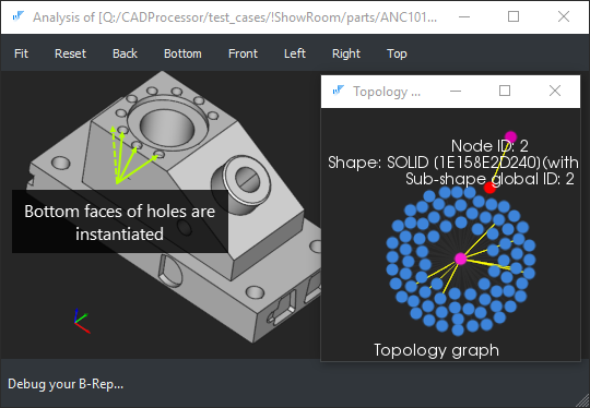 |
ANC101 part created with OpenCascade kernel. This part uses instancing in its features. |
Another remarkable observation is that the instancing per faces goes away once you write your model to STEP and restore it back. It seems that such instancing technique is not fully compatible either with the STEP format itself or with the implementation of STEP translator in OpenCascade.
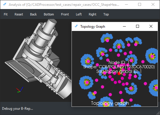 |
A mechanism with face instancing. In that case, the instantiated (i.e., located) faces have sole occurrences in the model. |
The impossibility to preserve the low-level instancing in the STEP format is actually disapproval for the whole idea. Who needs a sharing which cannot be communicated via the standard formats?
 |
The topology graph of the above mechanism after saving to STEP and restoring the model back. |
Our conclusion is the following. Even though the grammar of the B-Rep technology allows for the instancing of low-level boundary elements, that's probably not the best practice to follow in the standard two-manifold modeling. Yes, some modelers may reuse boundary elements or host geometries to stay more reliable in their internal computations, but there are some points you should be aware of:
- Instancing is a fragile matter. You cannot expect from all data translators to preserve instancing and even sharing at this level because the modeling kernels do not necessarily follow this principle. Of course, you are free to blame them, but the reality will not change anyhow.
- The idea of sharing of the higher-dimensional boundary elements is essential in non-manifold modeling. At the same time, in the typical two-manifold modeling, the idea of instancing looks weak and counter-intuitive. It is hard to imagine a real MCAD part that will really benefit from instancing its faces or any other boundary elements. Given the contemporary computational power, saving a couple of kilobytes at the price of higher complexity does not look attractive.
- The idea of instancing works much better at the upper layer of abstraction when we start dealing with assemblies. In the assembly modeling, the technique of instancing allows for the multiple occurrences of a single component in a hierarchy of parts. For example, a component may be inserted into the assembly from an external catalog, and the instancing relation expresses the fact of insertion.
Let's wrap up. If you are going to put some locations to your boundary elements, stop doing so, relax, and think a bit. It is likely that you're doing some bad design now, and the location matrix which you want to apply is probably the location for a part as a whole. Keep things simple and spare your algorithms from running on tricky crafted data to stay on a safe side.